Practical Filters and Couplers: A Collection from Applied Microwave & Wireless
With contributions from more than 20 experts, these articles will show you how to use the latest design and testing techniques for filters, couplers and baluns.
This design uses resonators longer than the typical 45 degrees
By Richard M.Kurzrok, PE
From APPLIED MICROWAVE & WIRELESS, VOL. 12, NO. 11, NOVEMBER 2000
Combline band-pass filters [1] employ direct-coupled, air dielectric, TEM resonators whose magnetic and electric fields are in phase opposition. As a result, nominal 90 degree resonators become decoupled. Foreshortening of resonator lengths is necessary for a viable design.
A commonly used resonator length is 45 degrees [1], although the use of longer resonators has been suggested [2]. A more recent design [3] has used a resonator length of about 27 degrees. This article discusses tunable combline band-pass filters with 60 degree resonators.
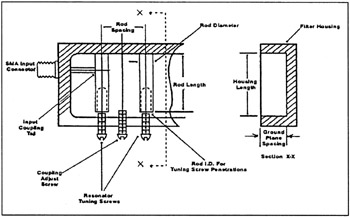
Many combline band-pass filters are fixed tuned to a specific center frequency. Other combline filters are factory adjusted or field tuned to a range of different center frequencies. Adjacent combline resonators provide maximum interstage coupling when the resonator length is close to 53 degrees. By using resonators of 60 degrees, tunability over a range exceeding 1.5 is readily achievable. Mechanical details of the tunable combline filter are shown in Figure 1. The filter uses slabline construction with round rods between ground planes. With the physical dimensions indicated in Table 1, a combline filter can be designed and constructed for a tuning range from 0.95 to 1.45 GHz.
| Dimension or Material | Value |
|---|---|
| Ground Plane Spacing | 0.625 inch |
| Resonator Rod... |