Practical Filters and Couplers: A Collection from Applied Microwave & Wireless
With contributions from more than 20 experts, these articles will show you how to use the latest design and testing techniques for filters, couplers and baluns.
By Randy Rhea
From APPLIED MICROWAVE & WIRELESS, VOL. 8, NO. 4, NOVEMBER/DECEMBER 1996
This design note describes a high performance low-pass filter that can be adapted for cutoff frequencies from 500 MHz to a few GHz. The filter is constructed from common hardware store items and only requires a soldering iron and hand saw for assembly.
The design begins with an L-C low-pass filter with element values determined by conventional techniques [1]. A 5th order Chebyshev low-pass with 0.1 dB pass band ripple and a cutoff of 800 MHz is shown in Figure 1 (4.56 pF, 13.6 nH, 7.86 pF, 13.6 nH and 4.56 pF).
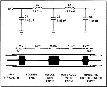
The shunt capacitors are realized as low impedance lines and the inductors are realized as high impedance lines using:
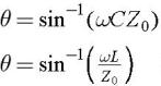
Z 0 is the characteristic impedance of the line that replaces a lumped element. Then the impedance is low for capacitive lines and the impedance is high for inductive lines, the electrical length of the line ( ?), is short and the best performance results.
#24 AWG wire (diameter=19 mils) is used for the coaxial high impedance lines. The outer conductor is a 9/32-inch brass tube (ID=0.25 inches) from K&S Engineering, stocked by many hardware and hobby stores. The resulting line impedance is 155 ohms. A brass-plated door hinge pin with a diameter of 230 mils is cut to the desired lengths to form 5-ohm low impedance lines.