Practical Filters and Couplers: A Collection from Applied Microwave & Wireless
With contributions from more than 20 experts, these articles will show you how to use the latest design and testing techniques for filters, couplers and baluns.
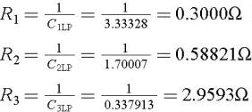
A Chebyshev high-pass filter with 20 dB gain and 0.25 dB of pass band ripple is to be designed. Since 20 dB corresponds to a linear gain of K 0=10, Table 4 (see appendix) can be used. The following values are given in the table:
C 1=3.33328 F
C 2=1.70007 F
C 3=0.337913 F
R 4=1 ?
R 5=9 ?
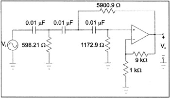
Using the transformed schematic shown in Figure 6, the new normalized values are:
C 1=1F
C 2=1 F
C 3=1F
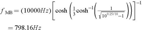
Suppose the filter should have ripple cutoff at 10 kHz. The filter is scaled as follows. The filter s ?3 dB cutoff first must be calculated:
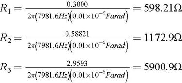
Next, the new cutoff is used to scale the components. We use 0.01 ?F for the capacitors and 1 kW for R 4 .
C 1= C 2= C 3=0.01 ?F
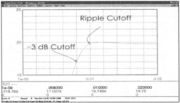
The final schematic is shown in Figure 7, with a simulated response from =SuperStar= [2] in Figure 8. The response figure shows T(s) in dB along the vertical axis, with frequency in MHz along the horizontal axis. The ripple cutoff is shown at 10 kHz (0.01 MHz in the figure). The predicted gain is 19.7499 dB at the cutoff, which is very close to the desired ripple value of 0.25 dB.