THE WATER ANALOG
Imagine a water pump system as shown in Fig. 2.1, with a handle (at the left) attached to a piston, being pushed toward the right-hand side. The water then comes out of a faucet, into an open pan, and one-way check valves prevent it from going in the wrong direction. When the handle is pulled back toward the left side, the water is sucked up into the pump again.
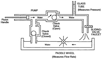 Figure 2.1: A water pump "analog" of a simple electronic system.
 Readers will intuitively have a good understanding of how this system would behave. That is, pushing harder on the handle would raise the pressure, and therefore the level of water would rise visibly in the glass tube. As the pressure is increased, the flow rate of water increases, as measured by the speed of the paddle wheel.
Alternatively, a different way to increase the flow rate would be to open the faucet more, by sliding the cross-hatched part of the valve toward the right. This decreases the resistance to flow.
The effects on flow rate as described above might be described mathematically by equation 2.1.
| (2.1) | 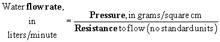
|
This equation assumes that the relationships are linear, and they actually are with water, as long as the flow rate is low.
The reason for bothering with all these pumps and valves is that the very familiar behavior of water is similar to the less familiar behavior of electricity. This similarity will aid in understanding...