SIMPLE RC FILTERS
A filter allows ac of some frequencies to pass through it with the amplitude (voltage or current) essentially unchanged, but the amplitudes of other frequencies are decreased. (An "active filter," involving transistors, can increase certain frequencies, as well as decreasing some.) A simple example, using just one resistor and one capacitor, which is called a "low-pass RC" filter, is shown in Fig. 11.1. It is a type of "first order Butterworth" filter.
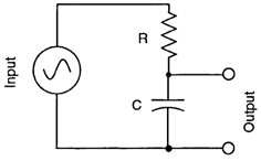 Figure 11.1: A first order Butterworth low-pass RC filter.
 As mentioned previously (pages 56 and 114), the circle symbol represents a source of ac voltage. The resistor and capacitor together make a voltage divider, similar to a potentiometer. However, the capacitor part of it resists the flow of current differently, varying according to the frequency of the ac. At higher frequencies, as discussed in Chapter 9, it allows more ac to go through it. In this diagram, the "output" voltage is therefore lower.
At low frequency, the capacitor acts as a very high resistance, and with dc it is an "open circuit" (essentially infinite resistance). Therefore, more voltage will appear across the output terminals hence the name "low-pass."
On page 99 of the Capacitors chapter, the concept of reactance was explained. This is a sort of effective resistance for a capacitor in an ac circuit, and its symbol is X C. Since the RC filter is similar to a potentiometer with a pair of resistors (page...