Industrial Electronics for Engineers, Chemists, and Technicians: With Optional Lab Experiments

Chapter 5: Series Resistances, Part II: Bad Measurements

EXPERIMENTS

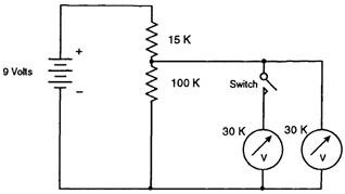
In the previous chapter, the experiments of Figs. 4.3 and 4.4 worked just as they should. Now let us try a similar setup, the one in Fig. 5.1, with higher resistance values. At first, just use the voltmeter to the right, and do not hook up anything where the left-hand voltmeter and switch are shown.


Figure 5.1: A voltage source with high output resistance, measured by a meter with a low input resistance.

The voltage measured should be around 9.5V(100K / 115K) = 8.3V, according to equation 4.3 on page 43. However, your actual measurement will be significantly lower more like 6 volts.

The experiments in the previous chapter were purposely designed to utilize very low values of resistance, in fact so low that the reader had to be cautioned not to leave the battery attached for a long enough time to overheat the resistors. In this chapter the resistors are relatively high values, so excess current is not a problem. A different problem appears in this case: low voltage. To illustrate it, attach another voltmeter, borrowed from a neighboring experimenter, or else use a resistor of 22K or 56K ohms. (Note that 56K is not a standard RETMA value, as listed on page 28, but it is often supplied in "assortments" of resistors anyhow. [*]) Alternately connecting and disconnecting this extra meter, using a clip lead instead of a real "switch," will show that the second meter pulls down the voltage even further, to about 4...

UNLIMITED FREE
ACCESS
TO THE WORLD'S BEST IDEAS

SUBMIT
Already a GlobalSpec user? Log in.

This is embarrasing...

An error occurred while processing the form. Please try again in a few minutes.

Customize Your GlobalSpec Experience

Category: Analog Voltmeters
Finish!
Privacy Policy

This is embarrasing...

An error occurred while processing the form. Please try again in a few minutes.