Accelerometers Information
 Accelerometers are transducers designed to measure acceleration forces. Accelerometers measure proper — also known as g-force — acceleration, which can be simply defined as "acceleration felt as weight." As its alternative terminology implies, proper acceleration is measured in g's. The "g" unit refers to the gravitational constant, which is approximately 32.2 ft/s2 (9.81 m/s2).
Proper acceleration is a type of relative acceleration measurement which uses a free-fall object — assigned a proper acceleration value of 0 — as its frame of reference. Because of this, gravitation and other natural forces have no effect on proper acceleration. An accelerometer at rest will return a value of approximately +1 g, as any point on Earth's surface is constantly accelerating upwards relative to a local free-falling object; for this reason, accelerometer output represents a value which has been "corrected" due to gravitational forces.
 While most modern accelerometers use semiconductors and piezoelectric means to measure acceleration, the image below describes the operation of a basic electromechanical linear accelerometer for reference.
The accelerometer in the image below uses the displacement of a solid mass relative to its container to measure differences in acceleration. In Image A, the container is at rest and the mass remains centered between two bars; in this state the accelerometer outputs a constant intermediate voltage. If the container accelerates in the direction of the bar to the right (shown in Image B), the inertia of the mass causes it to lag behind, compressing the spring behind it and stretching the one ahead of it. As this is occurring, the device registers a higher voltage relative to the acceleration measured. Upon deceleration, the mass returns to its resting position and the output voltage correspondingly decreases.
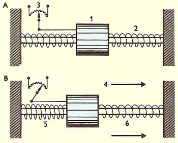
Basic electromechanical linear accelerometer.
Accelerometers can be constructed in various forms using different technological means. For specific types of accelerometers, please see the 'Sensor Types' section below.
Applications
Accelerometers are used in a wide range of applications over a variety of industries. Some example applications are listed below.
- Product testing (vehicle acceleration)
- Structure testing (buildings and bridges)
- Electronic devices (fitted to tablets and mobile phones to enable automatic shut down when dropped)
- Condition monitoring (vibration in pumps, compressors, fans, and other machinery)
- Remote marine animal tracking
- Seismology systems
- Inertial navigation systems
- Gravimetry
Specifications
Acceleration Amplitude and Frequency
When matching an accelerometer to an intended application, a buyer must consider the product's acceleration range and frequency. For measuring basic tilts, an accelerometer which measures ±1.5 g will suffice. A device which measures ±2 g is suitable for measuring the movement of robots, vehicles, or aircraft. For applications involving measurements of sudden stops or violent changes in direction, a ±5 g or greater accelerometer is recommended.
Accelerometers are also limited by the range of vibration frequency they can sense, and must be matched to the frequency of the intended application. The most sensitive accelerometers can detect vibration as low as 0.2 Hz, although they are typically inaccurate below frequencies of 10-15 Hz.
The graph below shows a typical frequency-sensitivity curve. The spike which occurs between 10,000 and 50,000 Hz is likely due to the accelerometer's natural frequency, at which point the sensor experiences a large increase in sensitivity, resulting in oversensitivity and possible saturation. Many devices feature filters which correct this oversensitivity.
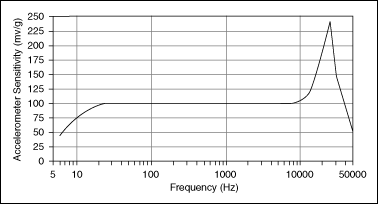
Accelerometer frequency-sensitivity curve from National Instruments.
Axes
When selecting an accelerometer, it is important to determine the number of axes the device is designed for.
- Single-axis accelerometers are among the most common types. They are often used to measure simple vibration levels. An example of a single-axis device can be seen in the image under 'Construction and Operation' above.
- Two-axis accelerometers are designed to measure acceleration or vibration along both an x- and y-axis (simply "forward, backward, and side-to-side").
- Three-axis devices add a vertical z-axis to the two-axis accelerometer. These are capable of complex 3-dimensional positioning and measurement. In lieu of a discrete three-axis accelerometer, a pair of two-axis accelerometers placed at right angles accomplish the same effect.
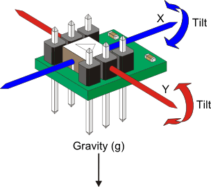
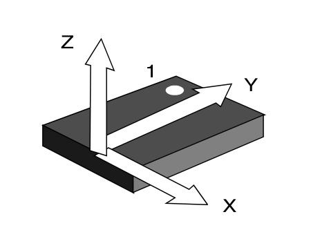
Diagrams illustrating the axes of 2-axis (left) and 3-axis accelerometers. This particular 2-axis sensor is also capable of tilt measurement.
Sensor Type
Accelerometers may use one of several technology types to sense and output changes in velocity and acceleration.
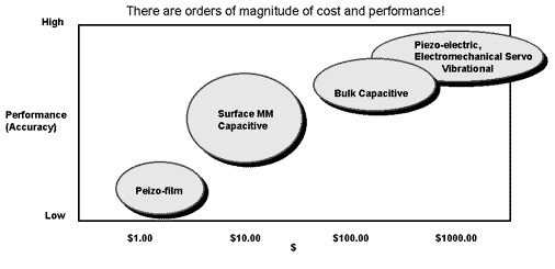
A graph showing the relative cost and accuracy of common accelerometer types.
Piezoelectric
Piezoelectric accelerometers rely on a piezoelectric material — typically a quartz crystal or polycrystalline ceramic material — to sense changes in acceleration. The piezoelectric effect refers to the accumulation of an electrical charge in a material due to mechanical stress. Piezoelectric accelerometers use some type of piezoelectric material in close proximity to a solid mass. When acceleration forces are applied to the device, the material responds to the compression or strain provided by the mass. Due to Newton's second law of motion (F=ma), the change in electric charge within the material is equal to the acceleration force acting against it, rendering the accelerometer an effective measurement device. Leads connected to the piezoelectric material then transmit the difference in charge and relay it to a signal conditioner or an amplifier to make the signal suitable for display or recording.
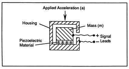
A basic diagram of a piezoelectric accelerometer.
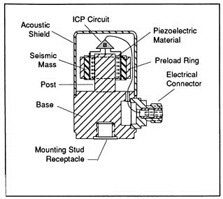
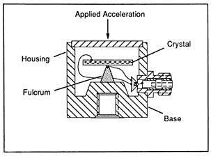
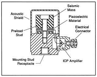
Within this basic framework, piezoelectric accelerometers may take many forms, each of which is suited to unique applications and environments. A few examples are listed in the table below.
|
Mode type |
Description |
Attributes |
Image |
|
Shear |
Piezo materials sandwiched between mass and center post; shear stress applied to materials. |
Excellent resistance to thermal interference; small size and profile. |
|
|
Flexural |
Beam-shaped piezo material supported by a fulcrum or similar object. |
Low profile; inexpensive; ideally suited to low frequency, low-g applications. |
|
|
Compression |
Piezo material arranged between mass and base, with an elastic stud supporting the mass. Available in upright, inverted (piezo material isolated from mounting base for greater accuracy), and isolated (mechanically and thermally insulated mass and piezo material) designs. |
Accurate and generally immune to various types of interference; suitable for high frequency and high-g applications; simple construction; high rigidity. |
|
Piezoresistive
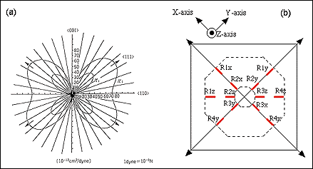
Piezoresistive accelerometers operate in a similar fashion to piezoelectric types, except that their output is measured as a change in resistance instead of electrical charge. These devices are typically manufactured as semiconductors, with separate resistive circuits for each axis to be measured. Each axis includes multiple piezoresistors, which decrease their resistive value when force is applied. Piezoresistive accelerometers are used in applications requiring measurement of high-g acceleration with a small sensor package.
The image below illustrates a design view of a typical three-axis piezoresistive accelerometer, showing (at right) that each circuit (or axis) is governed by four piezoresistors, labeled R1x, R2x, R1y, R1z, etc.
Capacitive
Capacitive accelerometers, sometimes known as capacitive mass-spring accelerometers, are semiconductor sensing devices. They consist of a silicon mass attached to four tethers, which collectively act as a spring system. When force is applied to one end of the mass, it moves and stretches the spring; the displacement of the mass therefore represents the measured acceleration. The displacement itself is measured using three capacitor plates: two fixed ones and a separate plate — located between the two fixed plates — which is attached to the mass. The inner capacitor moves with the mass, registering a change in capacitance relative to the fixed plates; this change is conditioned into a suitable output voltage to display or record acceleration data. Because the sensor's capacitance changes in relation to both fixed plates, these sensors can also output the direction of the acceleration.
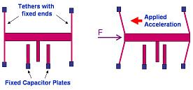
Capacitive accelerometer operation.
Other Types
Aside from the three types listed above, accelerometers may use any of the technologies listed below to measure acceleration.
- Fiber optic accelerometers use a fiber optic sensor to measure wavelength shifts as a result of applied forces.
- Hall effect accelerometers convert motion into electrical signals by sensing changes in a magnetic field.
- Heat transfer devices rely on the movement and location of a heated mass by sensing temperature.
- Magnetoresistive devices sense changes in material resistivity by using a magnetic field.
- Strain gage accelerometers convert the change in mass inertia into a strain measurement.
Standards
BS IEC 60747-14 -- Semiconductor accelerometers
IEEE 1293 -- Specification guide for single-axis nongyroscopic accelerometers
MIL-A-27261 -- Aircraft accelerometers
References
National Instruments - Accelerometer Principles
PCB Piezotronics - Introduction to Piezoelectric Accelerometers
Image credits:
Meggitt Sensing Systems | Sherborne Sensors | David Darling | National Instruments | Parallax | Kerry Wong | Texas Instruments | PCB Piezotronics | Sensors Magazine | Silicon Far East
- Acceleration
- Adhesive Base
- Battery Powered
- Biaxial
- Capacitance
- Corrosion Resistant
- Displacement
- Filters
- Integrated Electronics Piezo Electric (IEPE)
- Intrinsically Safe
- MEMS
- Magnetic Base
- Null-balance
- Piezoelectric
- Piezoresistive
- Radiation Hardened
- Resonance
- Sealed
- Self Test / Diagnostics / Self Calibrating
- Sensor / Transducer
- Single Axis
- Strain Gage
- Stud or Bolt-on
- Switch
- Temperature
- Transmitter
- Triaxial
- Velocity
- Wireless
- triaxial accelerometer
- MEMS accelerometer
- 3 axis accelerometers
- PCB accelerometer
- seismic accelerometer
- iepe accelerometers
- isotron accelerometer
- piezoresistive accelerometer
- accelerometer calibration
- accelerometer DC
- accelerometer tilt
- accelerometer USB
- accelerometer wireless
- accelerometers crossbow
- accelerometers for railroad
- angular acceleration sensors
- biaxial accelerometer
- fiber optic accelerometers
- high g accelerometers
- high temperature accelerometers
- ICP accelerometers
- ICP accelerometers price
- MEMS accelerometer comparison
- MEMS capacitive accelerometer
- piezo accelerometers
- piezoelectric accelerometer
- quartz flexure accelerometer
- SMT accelerometer
- ccld accelerometers
- lateral acceleration sensor
