Observe the rather awesome graphics of FIGURE (2). The millwright that will casually take on a problem of this magnitude is probably one of the following,
#1: Too inexperienced to realize the magnitude of the problem, or
#2: In the wrong business, or
#3: A reincarnation of Einstein, OR
#4: Any combination of the first three.
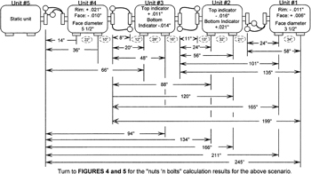 Figure (2)
 However, the millwright that s in the right business and experienced enough to use ample caution can use some of the formulas in the rest of this book to calculate the necessary shim packages. Correctly.
Unit #5 in FIGURES (1 and 2 ) is the fixed (static) unit. The other four units (currently not in alignment with each the other) are the movable units. A mess of numbers like this taken all in oneite would choke this mechanic to death. But taken one step at the time, the whole of the problem becomes mere applications and extensions of other problems and solutions described in this book.
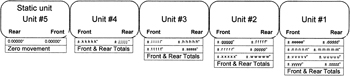 Figure (1)
 First, theoretically align unit one to unit two. Step #1: For now, disclaim the existence of units three, four and five. This simplifies the problem (temporarily) to a simple application of the format and formulas found in FIGURE (1) of the chapter: STANDARD RIM AND FACE ALIGNMENT. Use the applicable dimensions from FIGURE (2) in this chapter and the formulas from FIGURE (1) in the standard Rim and Face chapter:
| Note | FIGURE (2) include dimensions, but not the appropriate letters as... |
Copyright Tommy B. Harlon 2008 under license agreement with Books24x7