Armature To Field Coil Alignment is, in essence, an off-shoot of Field Coil TO Armature Alignment Conversely to the latter of the two (discussed in the previous chapter) assume the field coil housing to be the fixed unit.
For a believable scenario, assume the armature has been removed, transported to some shop, refurbished, reinstalled into the field coil shell, and you have been given the assignment of adjusting the clearance between the two components. M#1L and M#1R (terms frequently used in the previous chapter) are now simply measurements to the centers of the left and right bearing supports as viewed in FIGURE (1) . M#1L and M#1 R measurements are still to be taken, each beginning at the left side of the armature as shown. (Note the heavy black line on the north side of the armature from which to measure). From that point, it s simply a matter of plugging the variables from measurements A, B, C, D, E, M#1L, and M#1R into the appropriate formulas. Be cognizant this will be a shim correction in the vertical plane. The plus or minus shim package for the left bearing in FIGURE (1) is determined with the following formula:
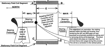 Figure 1
 Then, for the pedestal bearing on the right:
From FIGURE (1) , assume A, B, C, and D are .350", .230", .420", and .410" respectively. These readings (being taken at the 6 o clock and 12 o clock positions) indicate the need...
Copyright Tommy B. Harlon 2008 under license agreement with Books24x7