The classic, most often described and used Rim and Face format is the one described here in FIGURE 1 of this chapter. As pictorially presented, it simply means the dial indicators were arranged, tightened, and adjusted to zeroes at the (not shown) opposite position, then rotated 180 and are now shown in the correct reading position. The formulas described on the side of the motor ; while not unique to this indicator format, are none-the-less correct for this current FIGURE 1 indicator reading position. Such will be the trend for Rim and Face scenarios throughout this chapter; with a slight variation in the case of FIGURE 14 . (FIG. 14 appears twice)
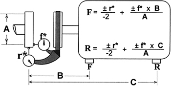 Figure (1)
 The pluses, minuses, or zeroes numerically or otherwise described for the applicable indicator format will be mimicked by one of the nine blocks on the page opposite the current drawing examples and/or verbiage. The broken lines represent the centerlines of the movable unit shafts. The heavy round dots on the broken lines mimic the axial addresses of the movable unit shim points (motor feet). Study the plus or minus numerically described readings pertaining to the current indicator format and find your matching block on the adjacent page. This will alert you to possible incorrect calculations, or help to verify correct shim calculations, making them more believable and understandable. However, if carefully calculated numbers, repeat: carefully-calculated-numbers belie the generic graph) vote for the numbers. The graphic symbols are only generic while the numbers are specific. This...
Copyright Tommy B. Harlon 2008 under license agreement with Books24x7