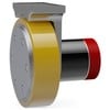
Refer to FIGURE (1) for a graphic view of the subject matter. Sometimes the driving unit will be several feet (even yards) from the driven unit and will require a special spool piece between the driver and driven couplings. This spool piece (sometimes called a Jackshaft) is usually hollow with rabbeted ends (sometimes referred to as boss-fits ) to assure concentric centerlines throughout the combined lengths of the spool piece and the two involved shafts.
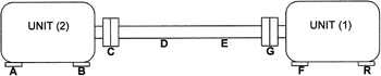 Figure (1)
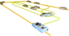
 Optical instruments are excellent tools for the initial installation of such units. However, ordinary dial indicators arranged in such a format as depicted in FIGURE (2) offer a much less expensive alternative to the (more costly) optical instrument along with the (usually quite expensive) personnel to operate said equipment. See FIGURE (2A) also. Formulas for four indicator arrangements are shown in FIGURES (3 , 4 , 5 , and 6 ). FIGURES (9 , 10 , 11 , and 12 ) show formulas for calculating shim packages for the A and B feet when unit #2 in the drawings are the movable units.
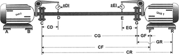 Figure (2)
 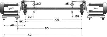 Figure (2A)
 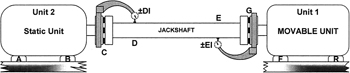 Figure (3)
 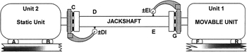 Figure (4)
 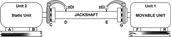 Figure (5)
 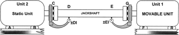 Figure (6)
 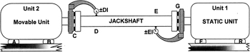 Figure (9)
 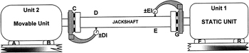 Figure (10)
  Figure (11)
 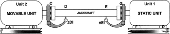 Figure (12)
 Indicator sag factors should be both pre-established and preloaded into the indicators when the readings are being taken. The formulas in FIGURES (3 , 4 , 5 , 6 , 9 , 10 , 11 , and 12 ) assume zero...
Copyright Tommy B. Harlon 2008 under license agreement with Books24x7