
Spur Gears Information
Last revised: February 3, 2025
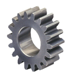
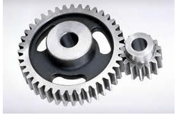
Spur gears are simple, easily manufactured gears and are usually the first choice when exploring gear options. Transmitting power between parallel axes, the teeth project radially on the disc. The sole variance in their identity remains the rack, which is covered more in-depth in Engineering360's Rack and Pinion Specification Guide.
Spur gears are regularly used for speed reduction or increase, torque multiplication, resolution and accuracy enhancement for positioning systems. The teeth run parallel to the gear axis and can only transfer motion between parallel-axis gear sets. Spur gears mate only one tooth at a time, resulting in high stress on the mating teeth and noisy operation.
Dimension Specifications
Gears mate via teeth with very specific geometry. Pitch is a measure of tooth spacing and is expressed in several ways.
Diametral pitch (DP) is the ratio of the number of teeth to the pitch diameter of a gear; a higher DP therefore indicates finer tooth spacing. It is easily calculated by the formula DP= (N+2) ÷ OD, where N is the number of teeth, and OD represents the circumferential measurement.
Circular pitch (CP) is a direct measurement of the distance from one tooth center to the adjacent tooth center. It can be measured by the formula CP= Π ÷ DP.
Module (M) is a typical gear discipline and is a measurement of the size and teeth number of the gear. Gears measured in inches earn 'English module' distinction to prevent confusion. M = OD ÷ N
Pressure angle is the angle of tooth drive action, or the angle between the line of force between meshing teeth and the tangent to the pitch circle at the point of mesh. Typical pressure angles are 14.5° or 20°.
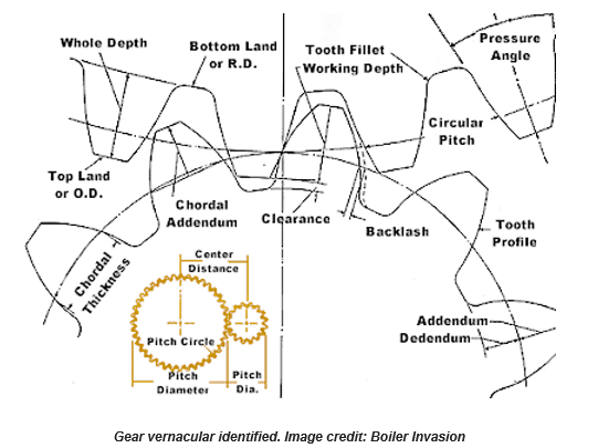
Selection tip: Gears must have the same pitch and pressure angle in order to mesh. Spur gears do not have helix angles.
Mounting Specifications
Consider the gear center, bore diameter and shaft diameter. The gear center can be a bored hole or an integral shaft. The bore diameter is the diameter of the center hole. The shaft diameter is the diameter of the shaft for gears with an integral shaft. Helical gears can be mounted on a hub or shaft. A hub is a cylindrical projection on one or both sides of a helical gear, often for the provision of a screw or other shaft attachment mechanism. Hubless gears are typically attached via press fit, adhesive or internal keyway.
Shaft mounting choices include the following:
|
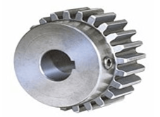
Keyway: One or more square cutouts exist in the gear bore for exact mounting on the shaft. |
|
|
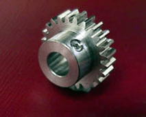
Set Screw: The gear is attached to the shaft by screws through the hub. |
|
|
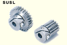
Hub Clamping Screws: The gear is attached with a screw that squeezes the inner diameter of the hub to a tight fit around the shaft. |
|
|
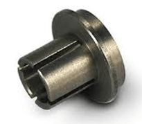
Split: The hub is split into several pieces that are tightened down by a separate clamp to grip the shaft. |
|
|
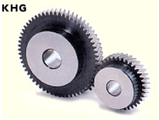
Simple bore: A straight bore designed for adhesive attachment |
|
Applications
The following application requirements should be considered with the workload and environment of the gear set in mind.
Power, velocity and torque consistency and output peaks of the gear drive so the gear meets mechanical requirements. Spur gears' design constraints limit their ability to transfer energy at high speeds and torques.
Inertia of the gear through acceleration and deceleration. Heavier gears can be harder to stop or reverse.
Precision requirement of gear, including gear pitch, shaft diameter, pressure angle and tooth layout.
Gear lubrication requirements. Some gears require lubrication for smooth, temperate operation.
Mounting requirements. Application may limit the gear's shaft positioning.
Noise limitation. Commercial applications may value a smooth, quietly meshing gear. Spur gears are particularly noisy in operation.
Corrosive environments. Gears exposed to weather or chemicals should be especially hardened or protected.
Temperature exposure. Some gears may warp or become brittle in the face of extreme temperatures.
Vibration and shock resistance. Heavy machine loads or backlash, the deliberate surplus space in the circular pitch, may jostle gearing.
Operation disruption resistance. It may be necessary for some gear sets to function despite missing teeth or misalignment.
Spur Gear Materials
Gear composition is determined by application, including the gear's service, rotation speed, accuracy and more.
- Cast iron provides durability and ease of manufacture.
- Alloy steel provides superior durability and corrosion resistance. Minerals may be added to the alloy to further harden the gear.
- Cast steel provides easier fabrication, strong working loads and vibration resistance.
- Carbon steels are inexpensive and strong, but are susceptible to corrosion.
- Aluminum is used when low gear inertia with some resiliency is required.
- Brass is inexpensive, easy to mold and corrosion resistant.
- Copper is easily shaped, conductive and corrosion resistant. The gear's strength would increase if bronzed.
- Plastic is inexpensive, corrosion resistant, quiet operationally and can overcome missing teeth or misalignment. Plastic is less robust than metal and is vulnerable to temperature changes and chemical corrosion. Acetal, Delrin, nylon, and polycarbonate plastics are common.
- Other material types like wood may be suitable for individual applications.
Spur Gears FAQs
What are the main components of a spur gear?
The main components include the addendum circle, pitch circle, clearance circle, dedendum circle, bottom land, top land, flank, and face. Important measurements include addendum distance, dedendum distance, clearance distance, circular pitch, and tooth thickness.
What is the efficiency of spur gear systems?
Spur gear systems have high efficiency levels, typically between 90% - 95% per gear train, including bearing losses.
How can spur gears be reverse engineered?
To reverse engineer spur gears, the process typically involves the following steps:
Use of Coordinate Measuring Machine (CMM)
A CMM is employed to accurately measure the dimensions of the gear. This machine, in conjunction with specialized gear software, helps determine the exact parameters of the spur gear, such as tooth thickness, pitch diameter, and other critical dimensions.
Specialized Gear Software
The software is used alongside the CMM to analyze the measurements and calculate the precise specifications of the gear. This is particularly important for custom gears where dimensions or tolerances may have been modified.
Simple Measuring Tools and Calculations
For standard gears, reverse engineering can be done using simple measuring tools and basic calculations. However, this method is limited to standard gears and may not be accurate for custom or modified gears.
Dedicated Gear Checker
In some cases, a dedicated gear checker may be used to verify the gear's parameters, ensuring that the reverse-engineered specifications match the original design.
What are the limitations of using simple measuring tools for reverse engineering gears?
Using simple measuring tools for reverse engineering gears has several limitations:
Accuracy Limitations
Simple measuring tools may not provide the high level of accuracy required for capturing the precise dimensions of a gear. This is particularly true for custom gears where dimensions or tolerances have been modified.
Complexity of Measurements
Gears have complex geometries, including parameters like tooth thickness, pitch diameter, and pressure angles, which may be difficult to measure accurately with basic tools.
Standard Gears Only
This method is generally limited to standard gears. Custom or modified gears require more sophisticated equipment like a Coordinate Measuring Machine (CMM) to ensure accurate reverse engineering.
Potential for Human Error
Manual measurements are prone to human error, which can lead to inaccuracies in the reverse-engineered specifications.
Lack of Comprehensive Data
Simple tools may not capture all necessary data points, such as the exact profile of the gear teeth, which are crucial for precise replication.
These limitations highlight the importance of using advanced tools and techniques, such as CMMs and specialized software, for accurate reverse engineering of gears.
How are Coordinate Measuring Machines (CMM) used in gear reverse engineering?
To reverse engineer spur gears using Coordinate Measuring Machines (CMM), the process involves several key steps and considerations:
Precision Measurement
A CMM is used to accurately measure the dimensions of the gear. This machine provides high precision, which is crucial for capturing the exact parameters of the gear, such as tooth thickness, pitch diameter, and other critical dimensions.
Integration with Specialized Software
The CMM is often used in conjunction with specialized gear software. This software analyzes the measurements taken by the CMM and calculates the precise specifications of the gear. This step is particularly important for custom gears where dimensions or tolerances may have been modified.
Handling Complex Geometries
Gears have complex geometries, including parameters like pressure angles and tooth profiles, which can be accurately captured using a CMM. This capability is essential for ensuring that the reverse-engineered gear matches the original design specifications.
Verification and Validation
After the initial measurements and calculations, a dedicated gear checker may be used to verify the gear's parameters. This ensures that the reverse-engineered specifications align with the original design, providing a reliable basis for manufacturing or further analysis.
What are the differences between spur gears and helical gears?
Here are some key differences between spur gears and helical gears:
Teeth Orientation
Spur Gears: The teeth are straight and parallel to the axis of rotation. This design allows for simple manufacturing and efficient power transmission between parallel shafts.
Helical Gears: The teeth are angled, forming a helix shape. This orientation allows for smoother and quieter operation as multiple teeth are engaged at once, distributing the load more evenly.
Load Distribution
Spur Gears: The entire transmission load is carried by one tooth at a time, which can lead to higher stress and noise, especially at higher speeds.
Helical Gears: Multiple teeth are engaged simultaneously, which reduces shock loads and noise. This makes helical gears suitable for applications requiring higher speeds and quieter operation.
Efficiency and Noise
Spur Gears: Known for high efficiency, typically between 90% - 95%, but can be noisy due to the backlash between teeth.
Helical Gears: Generally quieter than spur gears due to the gradual engagement of teeth, which reduces noise and vibration.
Applications
Spur Gears: Optimal for applications with slow-to-moderate speeds and torque. They are commonly used in situations where noise is not a critical factor.
Helical Gears: Preferred for applications requiring higher speeds and torque transmission, as well as quieter operation. They are often used in automotive transmissions and other high-speed machinery.
What are the advantages of using helical gears over spur gears?
Here are the advantages of using helical gears over spur gears:
Smoother and Quieter Operation
Helical gears have teeth that are angled, forming a helix shape. This design allows for a gradual engagement of the teeth, which reduces shock loads and noise compared to spur gears, where the entire load is carried by one tooth at a time.
Higher Load Capacity
The angled teeth of helical gears enable multiple teeth to be engaged simultaneously. This distributes the load across more surfaces, reducing stress on individual teeth and allowing for higher load capacities compared to spur gears.
Suitability for High-Speed Applications
Due to their smoother operation and reduced noise, helical gears are more suitable for applications requiring higher speeds and torque transmission. They are often used in automotive transmissions and other high-speed machinery.
Reduced Backlash
The design of helical gears helps in reducing backlash, which is the surplus space between gear teeth. This contributes to more precise and efficient power transmission.
Spur Gears Media Gallery
References
GlobalSpec—Gears 101: Spur Gears vs. Helical Gears
GlobalSpec—Standard Handbook of Machine Design, 3rd Edition
- stock spur gears
- pinion wire
- double spur gears
- large spur gears
- module 1.5 spur gears
- off the shelf spur gear
- 10 tooth spur gears
- 50 tooth gear
- AutoCAD mechanical spur gears
- compound spur gear
- high torque spur gears
- metric plastic spur gears
- module 1.25 spur gears
- module 3 spur gears
- module 4 spur gears
- module 5 spur gears
- module 8 spur gears
- phenolic spur gears
- small brass spur gears
- stock metric spur gears