
Rack and Pinion Gears Information
Last revised: January 29, 2025
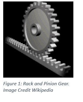
Rack and pinion gears are used to convert rotation into linear motion. The flat, toothed part is the rack and the gear is the pinion. A piston coaxial to the rack provides hydraulic assistance force, and an open centered rotary valve controls the assist level. A rack and pinion gears system is composed of two gears. The normal round gear is the pinion gear and the straight or flat gear is the rack. The rack has teeth cut into it and they mesh with the teeth of the pinion gear.
A ring and pinion gear is the differential's critical point of power transfer. A ring and pinion gear set is one of the simplest performance modifications that can be performed on a vehicle. The most common reason to change ring and pinion ratios from the original equipment is to retain power when bigger tires are put on a vehicle. The torque can be increased by a ratio change when there is enhanced pulling or higher take off power from a dead start. A well designed mechanism such as the rack and pinion gears save effort and time.
Product Selection
The Engineering360 SpecSearch database allows industrial buyers to select rack and pinion gears by gear type, configuration, and performance specifications.
Gear Types
Rack and pinion gears are available in three variations:
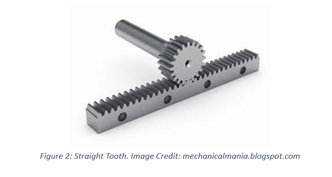
- Straight teeth have the tooth axis parallel to the axis of rotation. Straight teeth that run parallel to the axis of the gear. Load movement or transfer is manual or walk-behind.
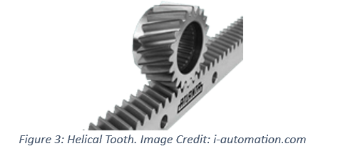
- Helical teeth gears provide continuous engagement along the tooth length and are often quieter and more efficient than straight tooth gears. Helical tooth gears resemble spur gears in the plane of rotation, but include teeth that are twisted along a helical path in the axial direction.
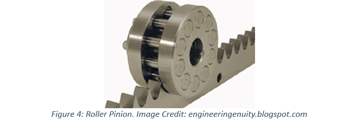
- Roller pinion drives use bearing supported rollers that mesh with the teeth of that rack in order to provide minimal to no backlash.
Quality
Rack and pinion gears variations are available in different qualities,
- 9/10 milled teeth are milled and hardened quality
- 7/8 precision cut or precision cut and hardened quality
- 5/6 teeth hardened and ground quality
Performance Specifications
The speed with which the rack moves as the pinion turns is determined by the diameter of the gear.
Application
Rack and pinion gears provide a less mechanical advantage than other mechanisms, but greater feedback and steering sensation. A rack and pinion gear gives a positive motion especially compared to the friction drive of a wheel in tarmac. In a rack and pinion railway, a central rack between the two rails engages with a pinion on the engine allowing a train to be pulled up very steep slopes.
Rack and pinions gears are commonly used in the steering system of cars to convert the rotary motion of the steering wheel to the side to side motion in the wheels. The steering wheel rotates a gear which engages the rack. As the gear turns, it slides the rack either to the right or left, depending on which way the wheel is turned. Rack and pinion gears are also used in some scales to turn the dial that displays a weight.
Rack and Pinion Gears FAQs
How do rack and pinion gears achieve zero backlash?
Rack and pinion gears can achieve zero backlash through specific configurations and mechanisms designed to preload the system. Here are the methods used to achieve zero backlash:
Split-Pinion Configuration
This method involves using a split pinion that contains a torsion spring or another anti-backlash mechanism. The split pinion is designed to load both sides of the rack simultaneously, effectively eliminating backlash by maintaining constant contact with the rack teeth.
Dual-Pinion Configuration
In this setup, a dual-pinion system is used to preload the axis. The preload can be set either mechanically or electrically. This configuration ensures that the preload is always present, independent of the rack's mounting accuracy, thereby eliminating backlash.
Mechanical Preloading
This involves a drive pinion and a second preload pinion along with a gearbox. The preload assembly applies an opposing force to the drive assembly, maintaining preloading and eliminating backlash.
These configurations are designed to ensure that the rack and pinion system operates smoothly without the play or slack that can lead to backlash, which is crucial for applications requiring high precision and accuracy.
Are rack and pinion gears limited in their applications?
No, rack and pinion gears are versatile and can be used in a wide range of applications, from simple, low-accuracy tasks to demanding high-precision tasks.
How do rack and pinion gears work in automotive steering systems?
Rack and pinion gears play a crucial role in automotive steering systems by converting the rotary motion of the steering wheel into the linear motion needed to turn the vehicle's wheels. Here's how they work:
Steering Wheel Rotation: When the driver turns the steering wheel, it rotates a pinion gear. This pinion gear is a small, round gear that meshes with the teeth of a linear gear rack.
Gear Engagement: The pinion gear engages with the rack, which is a flat, toothed component. As the pinion rotates, it moves the rack either to the left or right, depending on the direction the steering wheel is turned.
Linear Motion: The movement of the rack translates the rotary motion of the steering wheel into linear motion. This linear motion is what ultimately moves the wheels of the vehicle to steer it in the desired direction.
Efficiency and Precision: Rack and pinion systems are known for their efficiency and precision in steering applications. They provide a direct and responsive steering feel, which is why they are commonly used in modern vehicles.
What are the advantages of using helical tooth gears over straight tooth gears?
Helical tooth gears offer several advantages over straight tooth gears, particularly in terms of performance and efficiency. Here are some key benefits:
Continuous Engagement: Helical tooth gears provide continuous engagement along the tooth length, which results in smoother operation compared to straight tooth gears. This continuous engagement helps in distributing the load more evenly across the gear teeth.
Noise Reduction: Due to their design, helical gears operate more quietly than straight tooth gears. The angled teeth engage gradually, reducing the impact and noise typically associated with gear operation.
Efficiency: Helical gears are generally more efficient than straight tooth gears. The gradual engagement of the teeth reduces friction and wear, leading to improved efficiency and longer gear life.
Load Capacity: The design of helical gears allows them to handle higher loads compared to straight tooth gears. This makes them suitable for applications requiring high torque and power transmission.
These advantages make helical tooth gears a preferred choice in many applications where noise reduction, efficiency, and load capacity are critical considerations.
What are the differences between roller pinion drives and traditional rack and pinion systems?
Backlash
Roller Pinion Drives: These systems use bearing-supported rollers that mesh with the teeth of the rack, providing minimal backlash. This design helps in achieving high precision and smooth operation.
Traditional Rack and Pinion Systems: These systems can achieve zero backlash through specific configurations such as split-pinion or dual-pinion setups, which preload the axis mechanically or electrically.
Load Capacity and Stiffness
Roller Pinion Drives: While they offer minimal backlash, roller pinion drives may have lower load capacity and stiffness compared to traditional rack and pinion systems.
Traditional Rack and Pinion Systems: These systems are generally more robust in handling higher loads and providing greater stiffness, making them suitable for high-load applications.
Design and Operation
Roller Pinion Drives: The use of rollers allows for smoother and quieter operation due to the rolling contact, which reduces friction and wear.
Traditional Rack and Pinion Systems: These systems rely on direct gear-tooth engagement, which can be noisier and may require more maintenance to manage wear and tear.
How do preload configurations work in rack and pinion systems?
Preload configurations in rack and pinion systems are designed to eliminate backlash, which is the play or slack between the gear teeth that can affect precision and performance. Here are the main preload configurations used in rack and pinion systems.
Split-Pinion Configuration
This method involves using a split pinion that contains a torsion spring or another anti-backlash mechanism. The split pinion is designed to load both sides of the rack simultaneously, effectively eliminating backlash by maintaining constant contact with the rack teeth.
Mechanical Preloading
In this configuration, a drive pinion and a second preload pinion are used along with a gearbox. The preload assembly applies an opposing force to the drive assembly, maintaining preloading and eliminating backlash. This ensures that the system operates smoothly without the play that can lead to backlash.
Dual-Pinion Configuration
This setup uses a dual-pinion system to preload the axis. The preload can be set either mechanically or electrically, and it remains independent of the rack's mounting accuracy. This configuration ensures that the preload is always present, thereby eliminating backlash.
Rack and Pinion Gears Media Gallery
References
GlobalSpec—Rack and Pinion Drives Information