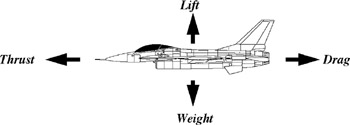
Introduction to Aeronautics: A Design Perspective, Second Edition

5.4: Drag Curves

5.4 Drag Curves

Consider again the case of steady, level, unaccelerated flight with the thrust vector aligned with the velocity. Figure 5.12 illustrates this situation. If the aircraft is in steady flight, not accelerating, forces must be in balance. Therefore, lift must equal weight, and thrust must equal drag. The lift requirement can be used to determine the required lift coefficient at any freestream velocity or Mach number:


Figure 5.12: Steady, level, unaccelerated flight.


Once C L is known, the aircraft's drag polar can be used to determine C D and then D at that velocity:


If the calculation of drag is performed for a range of velocities, and for a fixed aircraft weight and altitude, a drag curve is generated. The drag is also called thrust required T R because it is the thrust required from the engine to sustain steady, level flight for the given conditions. Figure 5.13 shows a drag curve for a typical subsonic aircraft. The drag is shown as the sum of parasite drag and induced drag. Note that parasite and induced drag are equal, each making up half the total drag, at the point on the curve where drag is a minimum. A thrust available model for an appropriately sized nonafterburning low-bypass-ratio turbofan engine [Eq. (5.11)] is also shown on Fig. 5.13. The thrust and drag curves are not drawn for velocities much faster than the speed where thrust available equals thrust required because the aircraft does not have enough...

UNLIMITED FREE
ACCESS
TO THE WORLD'S BEST IDEAS

SUBMIT
Already a GlobalSpec user? Log in.

This is embarrasing...

An error occurred while processing the form. Please try again in a few minutes.

Customize Your GlobalSpec Experience

Category: Wind Tunnel Testing Services
Finish!
Privacy Policy

This is embarrasing...

An error occurred while processing the form. Please try again in a few minutes.