Phase-Locked Loops for Wireless Communications: Digital, Analog and Optical Implementations, Second Edition
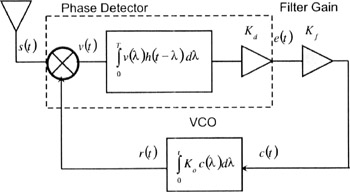
A complete Phase-Locked Loop (PLL) block diagram is shown in Figure 2.1. The PLL is receiving a signal s(t), with an unknown phase, ?( t). Viterbi [18] has described the phase-locked loop as a communications receiver that adjusts the local oscillator frequency and phase according to its measured phase error. Although PLLs are found in applications besides receivers, the PLL in Figure 2.1 is performing as a local oscillator to coherently demodulate the received signal. (Recall from communication theory that coherent demodulation provides a 3 dB improvement in signal-to-noise. In Chapter 11 we will show that the signal-to-noise improvement is 6 dB inside a synchronization loop.)
In Figure 2.1, we assign an amplitude,
, to the received signal, s(t), where P is the power in the signal. Initially, the magnitude
for the received signal may seem awkward. Recall however, the power in the signal x(t)= Acos(2 ?ft) is P = A 2/2. Algebraic manipulation yields A =
, the assumed magnitude for the input phasor in Figure 2.1. In some applications such as frequency synthesizers, the signal into the phase-locked loop has a fixed signal level and a high Signal-to-Noise Ratio (SNR). More stressful on loop performance however, are those applications with varying signal levels and low SNRs. In our subsequent derivations we will see that these two parameters affect the performance of the loop.
The phase detector for a...