Phase-Locked Loops for Wireless Communications: Digital, Analog and Optical Implementations, Second Edition
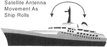
Third order phase-locked loops provide the desirable characteristic of being able to track an accelerating frequency input. In communications this occurs frequently when the receiver or transmitter is in motion. As an example, Figure 2.14 shows a satellite antenna on the mast of a ship. As the ship rolls with waves, the mast experiences a significant position displacement. The displacement is sufficient to generate a considerable frequency ramp. (32 Hz/sec is a common specification for UHF SATCOM receivers.)
An important class of receivers for the Global Positioning System (GPS) have significant Doppler induced by the satellites moving with respect to the receiver [5]. The rate of frequency change is dependent upon the satellite's relative position to the receiver.
A non-Doppler reason for using 3rd order phase-locked loops is that the filter can be used to optimize the phase noise performance of the loop. The 3rd order loop has an additional degree of freedom available to the designer attempting to optimize the phase noise contributions of different sources in the phase-locked loop. This will be discussed in Chapter 12.
Yet another advantage of the third order filter is in phase-locked modulators for Continuous Phase Modulation (CPM) waveforms. For frequency waveforms more complex than REC, [10] the accelerated phase during a symbol interval will create tracking errors for second order phase-locked loops.
With the...