Phase-Locked Loops for Wireless Communications: Digital, Analog and Optical Implementations, Second Edition
Chapter 9: All-Digital Phase-Locked Loops

In this chapter, we are going to extend our survey to loops that have do not have analog prototypes. Lindsey and Chie [1] performed a 1981 survey of digital PLLs that is recommended to the reader desiring additional architectures.

9.1 Non-Uniform Sampling

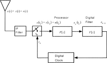
For all-digital phase-locked loops, there are alternatives to the sine and cosine based NCO as presented in Chapter 7. By utilizing sampling theory, it is possible to construct a phase-locked loop with a numerically controlled clock. Before discussing the architecture of a digital clock, we want to show the advantages of the concept. Figure 9.1 shows a phase-locked loop with a digital clock. Our derivation follows that of Chie in [2], which is similar to Weinberg and Liu [8]. (See also McCain, [3]).


Figure 9.1: Digital Clock in a Phase-Locked Loop [3]

In Figure 9.1, the sampler takes a sample of the bandpass signal at time t k. The time interval between samples is expressed as


The digital clock has a nominal clock period, T *, which is adjusted by the control input, e k?1, according to the equation


The control input, e k?1, to the digital clock in Figure 9.1 has an implicit delay. (It is physically impossible to have a discrete input dependent upon that input.) this is similar to the delay included for the NCO in Chapter 7. How the digital clock actually implements Equation 9-2 is deferred for later discussion in this chapter.

In order to...

UNLIMITED FREE
ACCESS
TO THE WORLD'S BEST IDEAS

SUBMIT
Already a GlobalSpec user? Log in.

This is embarrasing...

An error occurred while processing the form. Please try again in a few minutes.

Customize Your GlobalSpec Experience

Category: IC Phase-locked Loops (PLL)
Finish!
Privacy Policy

This is embarrasing...

An error occurred while processing the form. Please try again in a few minutes.