Phase-Locked Loops for Wireless Communications: Digital, Analog and Optical Implementations, Second Edition
A frequency synthesizer or signal source is expected to provide a pure spectral signal. There should be no unwanted amplitude or frequency/phase modulation in the output spectrum. As we will discuss shortly, undesired phase modulation on the local oscillator in cormnunications receivers, can reduce the channel selectivity and degrade the bit error rate of the receiver. It can also degrade the performance of coherent radars [14].
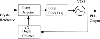
A simplified digital, synthesizer is shown in Figure 13.1. In instrumentation-grade synthesizers, the crystal reference oscillator typically provides a reference frequency of 10 MHz or 5 MHz. The voltage-controlled oscillator generally operates at a much higher frequency than the crystal reference. For example, a microwave synthesizer would have a VCO operating at frequencies above 9 GHz. Similar to all of the phase-locked loop discussions in this text, the VCO's output frequency is controlled by an error signal from the loop filter.
In Figure 13.1, the VCO's output frequency is divided by a ratio N in the digital counter. This can be a fixed integer N, or it can be changed to tune the VCO to different frequencies. As in all the PLLs, the phase detector generates an error voltage corresponding to the phase difference between the digital counter output and the reference oscillator (generally a stable crystal oscillator). Often the reference oscillator is thermally and physically isolated from the environment. Even in moderate mobile environments, platforminduced vibration of the reference oscillator...