In this chapter, we want to develop stability and frequency analysis tools for digital phase-locked loops similar to those developed for analog loops in Chapter 3. As with the analog loops, we will show the root locus is invaluable in determining stability.
8.1 Stability
In Figure 8.1, we have a system function labeled a phase-locked loop, although for the purposes of this discussion it could be any digital system with the system impulse function, h(n).
 Figure 8.1: Digital System for Stability Analysis
 The output, c(n), for Figure 8.1 is obtained by the convolution theorem,
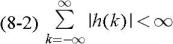
For Bounded Input-Bounded Output (BIBO) stability, the system of Figure 8.1 must have a bounded impulse function [1].
This is similar to the requirement for continuous systems, 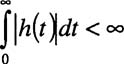 [8]. If the condition of Equation 8-2 is true, then the output, c(n), of Figure 8.1 is bounded. As an example, suppose we have a closed loop transfer function of the form,
A partial fraction expansion of Equation 8-3 yields
Hint: When performing a partial fraction expansion of an equation similar to Equation 8-3, it is best to divide out a "z" first, and then perform the partial fraction expansion on the quotient. After obtaining the partial fraction, then multiply it by z to obtain a form with a z in the numerators as in Equation 8-4. This places the intermediate results of the transformation into the form most often found in Z-Transform tables.
Using Z-Transform table, Appendix B, (or direct derivation) for Equation 8-4, we obtain

 TABLE OF CONTENTS