Phase-Locked Loops for Wireless Communications: Digital, Analog and Optical Implementations, Second Edition
Chapters 2 4 presented the analysis and design techniques for analog phase-locked loops. In this chapter we will review digital transform techniques so that we develop a similar analysis for digital phase-locked loops.
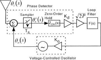
One of the first digital phase-locked loop configurations was a sampled version of an analog phase-locked loop [1], This architecture is still used in modems and synthesizers. Other applications include receivers for pulsed ? i( t) signals such as radar transmissions [9]. In Figure 5.1, we have taken a conventional analog architecture and added a sampler as our first example of a digital phase-locked loop.
Figure 5.1 is an architecture common in a receiver's frequency synthesizer. The primary difference between the configuration above and the complete analog phase-locked loop in Figure 2.1 is the digital phase detector which has a sampler and zero-order hold. We have replaced the 1/ s implicit VCO transfer function with V(s) because the derivations are more general if we use V(s). We will discuss the zero-order hold's transfer function, G zoh(s), in Example 5.1.
In Figure 5.1, there is a "star" superscript for ? e*( s), denoting the signal is sampled. In the communications literature, we typically assume the "star" superscript implies a complex conjugate, but the linear control literature uses this notation for a sampled function. An ideal sampler can be expressed as
where T s is the time interval...