In Chapter 2, the basic configurations for phase-locked loops were presented. In Chapter 3, we reviewed frequency analysis and stability, which allowed us to introduce design procedures for third order phase-locked loops. In this chapter, we will be examining the subtleties of phase-locked loop acquisition and tracking. In Chapter 2 and 3, we were interested in the linearized performance, but in this chapter, we want to examine acquisition, which requires consideration of the nonlinear phase detector.
The reader is cautioned not to be disheartened by the nonlinear equations presented early in this chapter, as they are only used to derive some estimating quantities for acquisition. For loop tracking, noise bandwidth, stability, etc, we will return to the linearized equations of Chapter 2.
4.1 First Order Acquisition
Figure 4.1 is a modification of the loop architecture that we evaluated in Chapter 2. The primary difference between Figure 2.2 and Figure 4.1 is the nonlinear function Sin[ ], within the modeled phase detector. The filter has also been changed to a generic F(s) instead of the fixed gain, K f, which was appropriate for a first order loop.
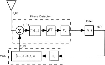 Figure 4.1: Nonlinear Phase-Locked Loop for Acquisition Analysis
 Note the VCO in Figure 4.1 includes a center frequency, f v. With a zero volt error input into the VCO (c(t)=0), the VCO produces the frequency f v. This permits the downconversion of the input signal without requiring large signal voltages into the VCO. (A 0 Hz ? VCO...
Copyright Kluwer Academic Publishers 2002 under license agreement with Books24x7


 TABLE OF CONTENTS