Serial Interfaces Information
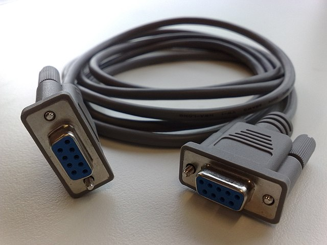
Figure 1: Serial interfaces provide a convenient and efficient option for allowing devices to be able to quickly and accurately communicate. Source: FAXE/CC BY-SA 3.0
For devices to work together, they must be able to communicate. Communication between devices requires standards and commonality to ensure information is shared properly and without error. Serial interfaces provide a convenient and efficient option for allowing devices to be able to quickly and accurately communicate.
Theory of Operation
Serial interfaces are used to transmit data between devices in a serialized, or sequential, manner. This is in contrast to parallel interfaces, where multiple bits are transmitted simultaneously over multiple lines. Serial interfaces have gained popularity due to their simplicity, lower cost, and ability to work over long distances. Below are some key points about how serial interface and serial communication work.
The Setup
Before the two devices can talk to each other, they need to agree on certain rules for communication This is the initialization phase. Both devices agree on parameters like the baud rate, which is essentially the speed of the conversation; the number of data bits, which is like the length of each sentence; and perhaps a parity bit, which serves as a quick integrity check used to make sure the message came through clearly.
Getting the Timing Right
Now, the communication must be synchronized. Imagine if you and a friend are on walkie-talkies; you say "over" to indicate you're done speaking. In the world of asynchronous serial interfaces, special bits known as the "start" and "stop" bits serve a similar purpose. They frame the data bits and signify the beginning and end of the data packet, respectively. In synchronous communication, a shared clock or a special sync byte acts as a conductor, ensuring both sides are always in tune.
The Conversation
Imagine one device, like a computer, wants to send a document to another device, like a printer. It takes the first chunk of data (maybe the document's title) and prepares it for transmission. The data is packaged between the start and stop bits and, if enabled, a parity bit is attached for error checking. This whole package is called a frame.
The computer's transmitter sends this frame over the wire. The bits flow like a stream of cars on a highway, arriving at the printer's receiver. The printer examines the start and stop bits to know when to start and stop listening, just like recognizing the word "over" on a walkie-talkie.
Integrity Check: Checking for Errors
The printer checks the parity bit, if it's included. If something doesn't add up, it knows an error occurred during transmission. This is like confirming with your friend to make sure you heard their message correctly.
Handshakes and Nods
Now, the printer needs a moment to process the received data and get ready for the next chunk. It uses flow control mechanisms — akin to a hand gesture or a nod — to signal the computer that it's okay to send the next frame. This could be a hardware-based handshake using specific signal lines or a software-based method using special control characters.
Ready for the Next One
Once the entire document is transmitted, the communication may either close or continue with other tasks, like sending a status report back to the computer. The cycle might repeat, following the same rules and protocols, ensuring a seamless dialogue between the devices.
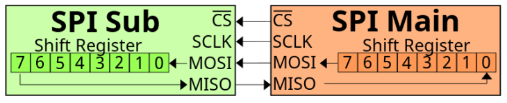
Figure 2: It uses flow control mechanisms — akin to a hand gesture or a nod — to signal the computer that it's okay to send the next frame. Source: Public domain
Specifications
The specifications for serial interfaces can vary depending on the type of interface in question. However, some general parameters often considered in serial interface specifications include:
Physical Layer Specifications
Defines the electrical characteristics such as voltage levels, impedance, and connector types.
Transmission Specifications
Serial interface specifications are dominated by specifications on the transmission itself. Common specifications include:
- Baud rate
- Data bits
- Parity
- Stop bits
- Flow control
- Buffer size
- Error checking
- Synchronization
Baud rate specifies the speed of data transmission, typically measured in bits per second (bps) while data bits define the number of bits in a data frame. It is common for a data bit to have 7 or 8 bits. Parity specifies whether parity checking is used, and if so, the type (odd, even, none).
Stop bits refers to the number of bits used to indicate the end of a data packet. Usually, this number is one or two. Flow control specifies if and how flow control is implemented, often through hardware (RTS/CTS) or software (XON/XOFF). Buffer size specifies the size of the data buffer used for temporary storage during transmission and reception. Error checking specifies the methods used for error detection and correction, if applicable. Finally, synchronization defines whether the communication is synchronous (with clock) or asynchronous (without clock).
Maximum Distance
The maximum allowable distance depends greatly on the interface type. Maximum distance can range from 50 feet up to 4,000 feet.
Each type of serial interface has its own standards or specifications document that details these parameters and more. For example, RS-232 is defined by the TIA/EIA-232 standard, while USB has its specifications managed by the USB Implementers Forum (USB-IF). More information on standards is in the section below.
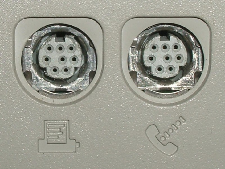
Figure 3: Serial interfaces come in various types. Source: Public domain
Types
Serial interfaces come in various types, each with its own set of characteristics, advantages, and disadvantages. Here are some of the most commonly used types of serial interfaces:
RS-232 (Recommended Standard 232)
Used for point-to-point communication, RS-232 is typically seen in applications with short distances. Data rates can be 115,200 bps or higher. The physical layer uses voltage-based signaling, often with DB9 or DB25 connectors.
RS-422 (Recommended Standard 422)
Used for either point-to-point or multi-drop (one transmitter, multiple receivers) communications, RS-422 can reach data rates up to 10 Mbps. The physical layer relies on differential signaling for noise immunity.
RS-485 (Recommended Standard 485)
Used for multi-point communication over long distances, RS-485 can also achieve data rates up to 10 Mbps. The physical layer uses differential signaling and can be half or full duplex.
Universal Asynchronous Receiver/Transmitter (UART)
UART is used for asynchronous serial communication between devices or ICs. The data rate varies and is often configurable. The physical layer usually relies on transistor-transistor logic (TTL) levels.
USART (Universal Synchronous and Asynchronous Receiver/Transmitter)
Commonly used in both synchronous and asynchronous serial communication, USART also has data rates that vary and are often configurable. The physical layer is similar to UART but with synchronous capabilities.
Serial Peripheral Interface (SPI)
Commonly used for short-distance, full-duplex communication, SPI is found mainly in embedded systems. Data rates can be up to several mbps. The physical layer can be digital or use TTL levels.
I²C (Inter-Integrated Circuit)
Typically used in short-distance, multi-master, multi-slave communication, I2C has multiple possible data rates. The data rates are broken into different modes: Standard mode (100 kbps), fast mode (400 kbps), high-speed mode (3.4 Mbps). Digital, open-drain or open-collector signaling are the common implementations on the physical layer.
Universal Serial Bus (USB)
Commonly used in consumer products, USB provides general-purpose connection for peripherals. Data ranges from 1.5 Mbps (low speed) to 40 Gbps (USB4). The physical layer varies with version; connectors include Type A, Type B, Micro, Mini, and Type-C.
Serial ATA (SATA)
Used to connect storage devices like hard drives and SSDs, SATA data rates can reach up to 6 Gbps (SATA 3.0). Differential signaling is commonly used on the physical layer.
FireWire (IEEE 1394)
Used for video and data transmission, FireWire data rates can range from 100 Mbps to 3.2 Gbps. The physical layer varies, including 4-pin, 6-pin, and 9-pin connectors.
Musical Instrument Digital Interface (MIDI)
Musical instruments and computers often use MIDI for serial communication. The data rate is typically 31.25 kbps with a 5-pin DIN connector on the physical layer.
Each type of serial interface is designed for specific applications and environments, and they often differ in terms of data rates, distance capabilities, and physical/electrical characteristics.
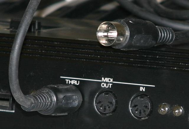
Figure 4: 5 pins DIN connector MIDI ports and cable .Source: PretzelPAws
Features
Serial interfaces come with a variety of features that make them suitable for different applications and environments. Here are some common features you'll find in various types of serial interfaces:
Basic Features
Simplex, duplex, and full duplex communication are the three types of communication commonly available for serial interfaces:
- Simplex: One-way communication, either from the transmitter to the receiver or vice versa
- Duplex: Two-way communication but not simultaneously
- Full duplex: Two-way communication that can occur simultaneously
Point-to-Point and Multi-Point Communication
Point-to-point communication occurs between two devices only. Multi-point communication allows multiple devices to communicate over the same data line.
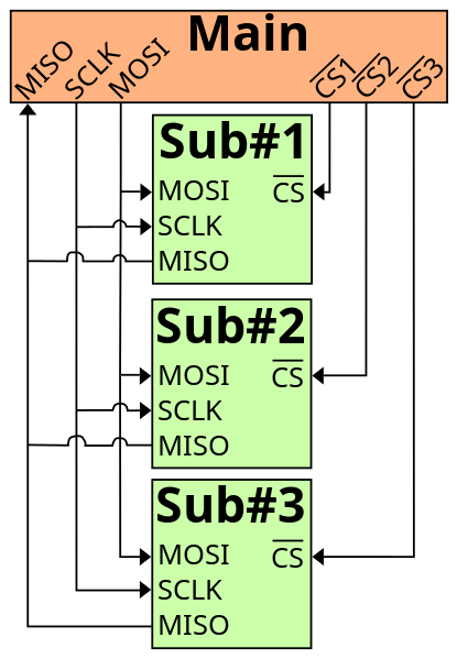
Figure 5: Keeping communication going requires knowing when to start and stop the conversation Source: Public domain
Synchronous and Asynchronous Modes
Keeping communication going requires knowing when to start and stop the conversation. Serial interfaces use two methods of timing:
- Synchronous: Data is sent based on clock signals
- Asynchronous: Data is sent without a clock, usually framed by start and stop bits
Data Framing
Consists of start bits, data bits, parity bits (optional), and stop bits to structure data packets.
Error Detection and Correction
Parity bits, checksums, and more advanced methods like Cyclic Redundancy Check (CRC).
Data Buffering
Temporary data storage to handle data rate mismatches between sender and receiver.
Addressing
In multi-point systems, devices may have unique addresses for targeted communication.
Differential Signaling
Used in some serial interfaces like RS-422 and RS-485 for noise immunity.
Signal Conditioning
Use of techniques to maintain signal integrity over long distances.
Hot Swapping
Ability to add or remove devices without shutting down the system (common in USB).
Plug and Play
Automatic configuration of parameters and drivers, commonly found in USB interfaces.
Power Over Data Lines
Some interfaces like USB can supply power along with data transmission.
Multi-Master and Multi-Slave Systems
More than one device can initiate communication (e.g., I²C).
Encryption
Data can be encrypted for secure transmission.
Authentication
Devices may need to authenticate each other before data exchange.
Data Integrity Checks
Advanced error-checking mechanisms to ensure data has not been tampered with during transmission.
Each type of serial interface may offer a subset of these features, depending on its intended application and design constraints.
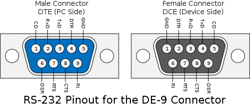
Figure 6: Each type of serial interface may offer a subset of these features, depending on its intended application and design constraints. Source: Rljacobson/CC BY-SA 4.0
Manufacture
The manufacturing of serial interfaces involves multiple steps and components, from conceptual design to final testing. Here are the main steps in the process:
- Specification development
- Schematic design
- Component selection and sourcing
- Mass production
- Assembly
- Testing
Engineers and designers establish the functional requirements and specifications for the serial interface, including data rates, physical layer requirements, and other features. Electrical schematics are drawn to outline how the circuit components will be connected.
Appropriate components like transceivers, connectors, resistors, and capacitors are selected based on the specifications. A circuit board layout is designed using CAD software. The board is manufactured, often using techniques like etching for printed circuit board (PCB) creation. Components are then soldered onto the boards.
The finished assemblies undergo testing to verify that they meet the design specifications. This could involve testing data rates, error rates, and other functional tests.
Manufacturing serial interfaces is a complex process that involves multiple disciplines including electrical engineering, computer science, material science, and industrial engineering.
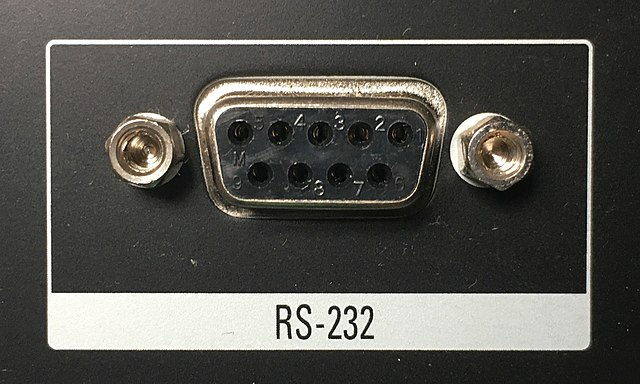
Figure 7: Serial interfaces are employed in a broad range of applications.Source: Pittigrilli/CC BY-SA 4.0
Applications
Serial interfaces are employed in a broad range of applications across various industries due to their versatility, simplicity, and cost-effectiveness. Here are some common applications:
Computing and Data Storage
Peripheral connections often rely on serial interfaces for communication. Connecting keyboards, mice, printers, and other peripherals to computers is often accomplished through interfaces like USB. Data transfer between computers and external storage devices like external hard drives typically relies on USB or SATA connections.
Industrial Automation and Control Systems
Serial interfaces like RS-485 are often used to connect programmable logic controllers (PLCs) in industrial settings. These settings often have a tremendous number of sensors and devices also. Gathering data from various sensors and sending it to a central system is often done with serial interfaces. Controlling the operation of industrial machinery is also a task for serial interfaces.
Telecommunications and Networking
Many routers and switches have RS-232 ports for initial setup and configuration. Older technology like dial-up and DSL modems used RS-232 extensively. In older systems, serial connections were used for transmitting data over long distances.
Medical Devices
Serial interfaces can be used to connect medical monitoring devices to computer systems. Devices like MRI machines may use serial interfaces for data transmission.
Consumer Electronics
Smartphones use USB for charging and data transfer. Cameras use USB or FireWire for data transfer to computers.
Embedded Systems and IoT
Microcontroller communication relies heavily on serial interfaces. UART, SPI, and I²C are commonly used for chip-to-chip communication in embedded systems. Many internet of things (IoT) devices use serial communication for sending sensor data to a central hub or cloud.
Aerospace and Defense
Serial buses are often used for intra-vehicle communication in aircraft. Satellites use serial interfaces for onboard data handling systems and communication with ground stations.
Entertainment and Media
Musical instruments often use MIDI to connect to computers and each other. Some older gaming systems also used serial connections for controllers.
Scientific Research
In scientific experiments, serial interfaces can be used to collect data from various instruments. In remote sensing and data collection, especially in harsh environments, serial interfaces provide means for telemetry.
Serial interfaces are incredibly versatile and continue to be integral in both legacy systems and modern technology.
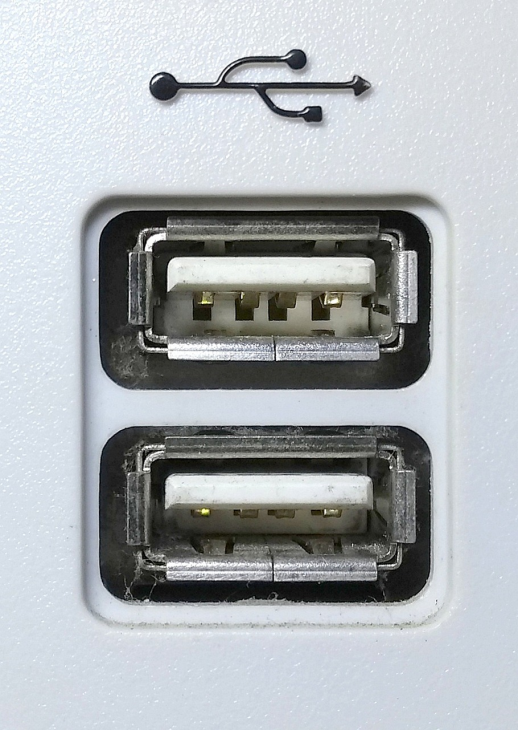
Figure 8: Various standards govern the design, implementation, and usage of serial interfaces. Source: Pixabay
Standards
Various standards govern the design, implementation, and usage of serial interfaces. These standards are typically set by industry organizations and ensure interoperability, reliability, and certain performance metrics. Here are some of the key standards that apply to different types of serial interfaces:
- RS-232 (Recommended Standard 232)
- RS-422 (Recommended Standard 422)
- RS-485 (Recommended Standard 485)
- UART (Universal Asynchronous Receiver/Transmitter)
- USART (Universal Synchronous and Asynchronous Receiver/Transmitter)
- SPI (Serial Peripheral Interface)
- I²C (Inter-Integrated Circuit)
- USB (Universal Serial Bus)
- ISO 7816 (Smart Cards)
- FCC Part 15
These standards are all incredibly important for ensuring devices can work together regardless of application or manufacturer. Many of these standards were originally defined by the Electronic Industries Association (EIA) and are now maintained by the Telecommunications Industry Association (TIA). Other standards are defined by the IC manufacturers and may follow proprietary standards. Other industry associations work to develop and maintain standards like the USB Implementers Forum (USB-IF)
These standards help to ensure that serial interfaces work reliably and are compatible with various devices and systems. Some standards are more formalized and governed by official bodies, while others may be de facto standards widely accepted by the industry.
References
Analog Devices—What is a Serial Interface?
Techopedia —What Does Serial Interface Mean?
TechTarget—What is a serial communications interface (SCI)?
RealPars—What is RS232 and What is it Used for?
CUI Devices—RS-485 Serial Interface Explained
Circuit Basics—Basics of the I2C Communication Protocol
How Stuff Works—How Serial Ports Work
eCFR—FCC Part 15—Radio Frequency Devices
Related Information
Electronics360—Menlo Micro addresses design, test and measurement needs for 5G and broadband wireless RF systems with the MM5140
- 10Base-T
- Bluetooth®
- C-UL US Listing Mark
- CE Conformity Marks
- CompactPCI (cPCI)
- DB25
- DB9
- DIN Rail Mounted
- Desktop / Tower
- ESD Protection
- FCC
- Fieldbus
- Indicators
- Modbus®
- PC/104 (PC/104-Plus, EBX, ETX)
- PCI
- PCMCIA (PC Card)
- Plug and Play
- Portable
- Printed Circuit Board (PCB)
- RJ-45
- RS232
- RS232/422/485
- RS422
- RS485
- Rack Mounted
- RoHS
- UL Listing Mark
- USB
- Wireless Link