Electromechanical Relays Information
 Electromechanical relays are electrically operated switches used to isolate circuits or batteries, detect faults on transmission and distribution lines, and control a high powered circuit using a low power signal. Simple relays consist of a magnetic core wrapped in a wire coil, a movable armature attached to an iron yoke, and one or more set of contacts. When an electric current passes through the coil it generates a magnetic field that activates the armature, therefore moving the contacts to make or break a connection.
The diagram below shows the parts of a relay and its operation. The relay on the left is off, meaning there is no current flowing to the coil. The relay on the right has switched on due to the energizing of the coil and subsequent movement of the armature and contact.
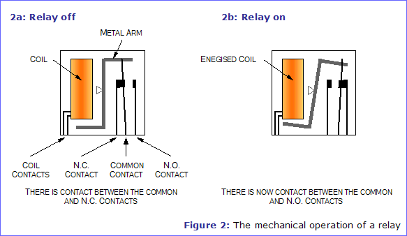
Image Credit: Electronics in Meccano
Types of Electromechanical Relays
Electromechanical relays can be classified by both application and device construction.
Reed Relays
Reed relays are comprised of a single reed switch enclosed in a solenoid. The switch's contacts are located inside a glass or ceramic tube for corrosion protection, and are comprised of magnetic material which is influenced by the field of the solenoid. Reed switches are capable of fast switching and require very little power from the control circuit, but may require more frequent maintenance due to magnetized reeds sticking in the "on" position.
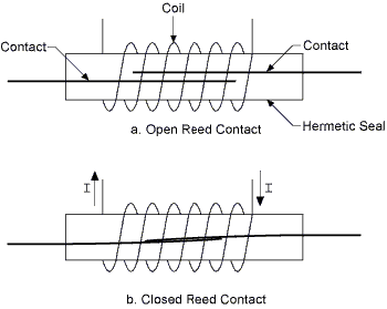
Reed relays in open and closed positions. Image Credit: National Instruments
High Voltage and Heavy Duty Relays
Heavy duty relays are often used for machine control and other industrial applications. They are made of durable, long-lasting materials and are often used to control starters and other components.
Relays designed for high voltage and high frequency applications are heavily insulated and use strong materials to increase contact life and withstand heavy use. They can typically withstand multiple kilovolt (kV) surges.
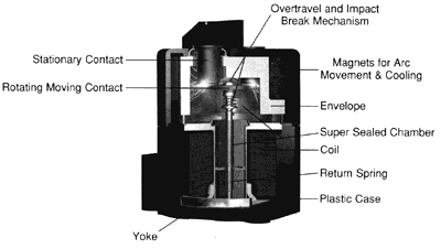
A high voltage relay design. Image Credit: TE Connectivity
Aerospace / MIL-SPEC Relays
Relays may be manufactured for aerospace and defense applications, and may also meet a number of U.S. military standards (MIL-SPEC). Common standards for relays include MIL-PRF-39016, M83536, and M83726.
Specifications
Mounting
Electromechanical relays may be mounted using a number of different methods.
-
Bracket (or flange) mounted relays are equipped with a flange for mounting. The flange is typically installed by bolting the device to a matching flange which is then welded to a corresponding wall.
-
DIN rail mounted devices are equipped with a fastener capable of mounting on a DIN rail. DIN rails are mounting devices standardized by the Deutsches Institut fur Normung (DIN).
-
Panel mount relays are manufactured for mounting to an electrical panel.
-
PCB relays are mounted on printed circuit boards (PCB) using through-hole contacts or surface mount technology (SMT).
-
Socket relays are mounted to PCBs using pin sockets.
 Switch Specifications
The GlobalSpec SpecSearch database contains information about a relay's switch, including the number of poles and throws.
Poles
The term "pole" describes the number of separate circuits controlled by a switch. The number of circuits controlled by the relay determines the number of switch contacts, which in turn determines the poles needed to make or break the contacts. Switches typically have between one and four poles.
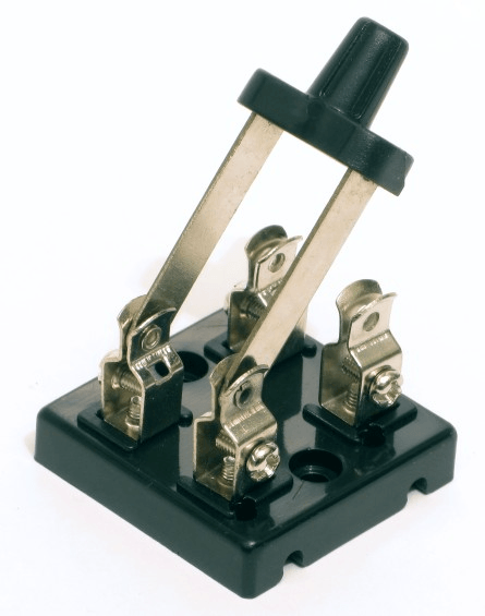
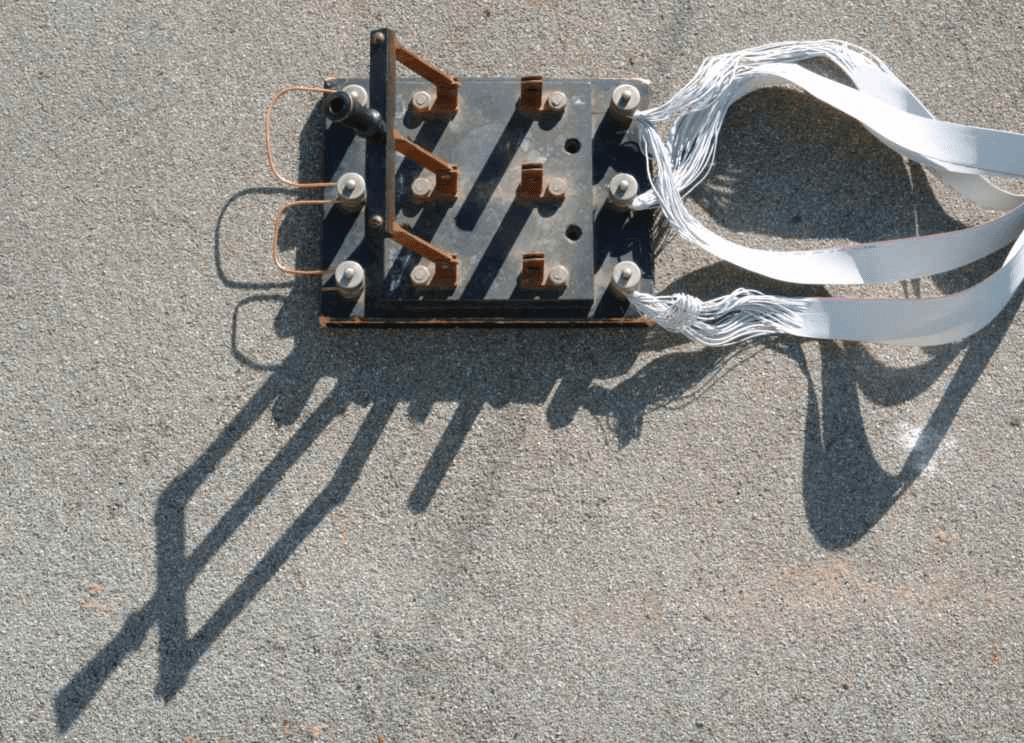
The image series below illustrates, from left to right, a single pole (SP), double pole (DP), and triple pole switch (3P). Note that, in the last image, the switch is connected to three separate circuits and has three contacts.
Throws
It is also important to consider a relay switch's throws, or the number of distinct positions a switch is capable of.
-
Single throw (ST) switches are open in one position and closed in another. For example, a single pole single throw (SPST) switch is a simple on-off switch, such as a light switch. A double pole single throw (DPST) switch is an on-off switch that opens and closes two contacts with a single motion.
-
Double throw (DT) switches are two-way devices. Double throw relays have three contacts and two positions: in the first position, Contacts 1 and 2 are in contact, but the third remains open. In the second position, this connection is reversed to Contacts 2 and 3.
Contacts
Specifications about contacts, including contact orientation and maximum ratings, are important to consider when selecting electromechanical relays.
 Contact orientation refers to the switch's position when a relay coil is not energized. As its name implies, a normally open (NO) switch is open in a resting, non-energized position; when current is passed through the relay, the switch then closes. A normally closed (NC) switch is therefore reversed: closed at rest, and open when energized. Changeover switches contain both NO and NC contact types.
Contacts are frequently rated to accept a maximum amount of current allowable under specified heat dissipation and ambient conditions. Maximum current is sometimes referred to as maximum switching voltage (expressed in volts) or maximum switching current.
Speed
A relay's speed specifications include make time and break time. Make time refers to the amount of time a switch needs to operate and make contact, while break time is the amount of time required to release and break contact. Switch speed is typically measured and specified in milliseconds. Higher speed devices have several advantages over lower speed ones. In low voltage applications, high speed relays reduce noise, while in high voltage applications fast switches reduce arcing and the possibility of physical damage.
Features
An electromechanical relay may feature one or many special attributes.
-
 Convertible contacts essentially feature adjustable contact orientation. For example, a normally open contact can be reconfigured to be normally closed, and vice versa.
 -
Current / voltage sensitive relays can indicate when a maximum current or voltage threshold is exceeded.
-
Relays with expandable decks allow for the addition of extra switch poles.
-
Intrinsically safe relays will not produce sparks or other thermal effects under conditions that may ignite a gas mixture. They are frequently used in explosion-proof applications.
-
Push-to-test devices allow manual operation using a pushbutton in order to test the relay circuit.
-
Relays featuring time delays have adjustable speeds, allowing for delayed make or break times.
Standards
BS EN 61810-1 -- Electromechanical elementary relays - Part 1: general requirements
SAE AS5363 -- General specification for electromechanical power controller/relay
References
National Instruments - How to Choose the Right Relay
Image Credits:
OMEGA Engineering, Inc. | Enasco | Skycraft Surplus | Frank Alapini
- Arkansas
- California
- Colorado
- Connecticut
- Florida
- Georgia
- Iowa
- Illinois
- Indiana
- Kansas
- Kentucky
- Louisiana
- Massachusetts
- Maryland
- Michigan
- Minnesota
- Missouri
- Mississippi
- North Carolina
- New Jersey
- Nevada
- New York
- Ohio
- Oklahoma
- Oregon
- Pennsylvania
- Rhode Island
- South Carolina
- South Dakota
- Tennessee
- Texas
- Virginia
- Washington
- Wisconsin
- > 4 Poles
- Aerospace / MIL-SPEC Relay
- Bracket (Flange) Mount
- Current Sensitive
- DIN Rail
- Double Pole (DP)
- Double Throw
- Four Pole (4P)
- General Application Relay
- High Voltage Relay
- Intrinsically Safe
- Latching Relay
- Machine Control (Heavy Duty) Relay
- PC Board
- Panel
- Push-to-Test Button
- Reed Relay
- Sealed Relay
- Single Pole (SP)
- Single Throw
- Socket or Plug-in Style
- Time Delay
- Triple Pole (TP)
- Visual Indicator
- latching relay
- 4PDT relay
- SIL 2 relay
- 12V miniature relay
- 20 amp relay
- 220 volt DPDT relays
- 24 volt DC DPDT relays
- 50 amp DPDT relays
- 50 amp relay
- class b relay
- form d relay
- high voltage DPDT relays
- MIL-SPEC time delay relay
- modular step relay
- power relay manufacturers
- RF DPDT relays
- SIL 3 relay
- SIP relay
- slim line relay
- telephone switching relay
- two stage relay
- ultra miniature relay
