RF Diodes Information
Last revised: December 4, 2024
Reviewed by: Scott Orlosky, consulting engineer
RF diodes are designed to handle high-power radio frequency (RF) signals in stereo amplifiers, radio transmitters, television monitors, and other RF or microwave devices.
Types
PN junction diodes or general purpose diodes are designed for general-purpose applications.
Schottky barrier diodes (Schottky diodes, Schottky diodes) are used mainly in high-frequency and fast-switching applications.
PIN diodes are used as either switches or attenuator elements.
Varactor diodes can be used in electronic tuning systems to eliminate the use of and need for moving parts.
Step-recovery diodes are designed for very high frequency (VHF) and fast-switching applications.
Tunnel diodes and Gunn diodes are used in oscillators and other RF applications.
Impact ionization avalanche transit-time (IMPATT) diodes are also designed to operate at very high frequencies. Typically, these RF diodes are used as elements in either RF or microwave devices.
Specifications
Specifications for RF diodes include:
- Forward voltage
- Maximum allowable reverse voltage
- Reverse current
- Repetitive peak reverse voltage
- Maximum reverse voltage
- Peak forward surge current
- Power dissipation
- Operating frequency
- Terminal capacitance
- Junction operating temperature
- Diode application
Categories
Typically, RF diodes are categorized as:
- Amplification diodes
- Detector diodes
- Mixer diodes
- Damper diodes
- Limiter diodes
- Switching diodes
- Microwave diodes
- Modulation diodes
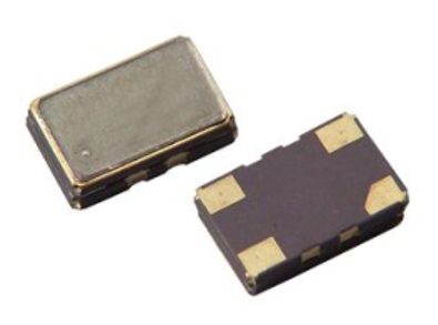
IC Package Types
RF diodes use many different IC package types.
Diode outline (DO) — DO-4, DO-5, DO-8, DO-9, DO-15, DO-27, DO-34, DO-35, DO-41 and DO-201 are diode outline (DO) packages
Small outline diode (SOD) — SOD-80, SOD-106, SOD-123, SOD-323, and SOD-523 are small outline diode (SOD) packages.
Transistor outline (TO) — TO-3, TO-66, TO-92, TO-202, TO-220, TO-237 and TO-247 are transistor outline (TO) packages.
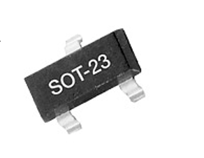
Small outline transistor (SOT) — SOT23, SOT26, SOT89, SOT143, SOT223, SOT323, SOT343, SOT346, SOT353, SOT363, SOT416, SOT457, and SOT523 are small outline transistor (SOT) packages.
Discrete package (DPAK) — D2PAK is a large surface-mounted package that includes a heat sink. SC-59, SC-74, and SC-76 are plastic, surface-mounted packages with three leads.
Metal electrode leadless face (MELF) — MELF packages for RF diodes include QuadroMELF, MicroMELF, and MiniMELF.
Standards
MIL-STD-35-54 — Tunnel semiconductor diode.
RF Diodes FAQs
What is the role of PIN diodes in RF applications?
A PIN diode consists of a wide, undoped intrinsic semiconductor region between a p-type and an n-type semiconductor region. This structure differentiates it from a standard PN junction diode.
The intrinsic layer allows the PIN diode to function as a variable resistor at radio and microwave frequencies, with resistance determined by the forward-biased direct current.
Switching: PIN diodes are commonly used as RF switches. They can control large RF signals with smaller levels of direct current excitation, making them suitable for applications where fast switching is required, such as in combined receiver/transmitter antenna circuits.
Attenuation: They are also used in RF attenuators. By adjusting the current through the diode, the amount of signal attenuation can be varied, allowing for precise control of signal levels without introducing distortion.
Relayless Switching: In modern radio transceivers, PIN diodes enable relayless switching between receive and transmit states, as well as the selection of IF or front-end bandpass filters.
The intrinsic region provides a greater separation between the p and n regions, allowing higher reverse voltages to be tolerated and making the diode suitable for high-voltage applications.
Their ability to handle high-power RF signals makes them ideal for RF applications, although they are not suitable for lower frequencies where they function as rectifiers.
What are the limitations of using PIN diodes in RF applications?
There is a trade-off between insertion loss and capacitance. As the forward series resistance (RF) decreases, the capacitance (CT) increases. A low value of CT is crucial for maintaining good broadband isolation properties, which can be a limiting factor in some applications.
The linearity of the PIN diode is an important parameter for maintaining signal integrity in many applications. Additionally, switching time is critical, especially in applications like combined receiver/transmitter antenna circuits where fast switching is necessary.
What are the advantages of using PIN diodes over other types of diodes in RF applications?
PIN diodes function as variable resistors at radio and microwave frequencies. This property allows them to control RF signal levels without introducing distortion, which is crucial for maintaining signal integrity in RF applications.
They are capable of controlling relatively high-power RF signals, making them suitable for applications that require handling large RF signals with smaller levels of direct current excitation.
PIN diodes have low levels of capacitance, which is beneficial for RF applications where maintaining good broadband isolation properties is important.
They are widely used as RF switches and in variable attenuators. Their ability to switch and vary attenuation makes them versatile components in RF circuits.
The intrinsic region in PIN diodes provides greater separation between the p and n regions, allowing them to tolerate higher reverse voltages compared to standard diodes.
What factors should be considered when selecting RF components?
Frequency Range
Ensure the RF component is suitable for the frequency range of your application. For example, PIN diodes are not suitable for lower frequency applications.
Consider the power levels the component can handle. PIN diodes, for instance, are capable of controlling relatively high-power RF signals, which is crucial for applications requiring large RF signal handling.
Evaluate the trade-off between insertion loss and capacitance. A low insertion loss is desirable, but as the forward series resistance (RF) decreases, capacitance (CT) increases, which can affect broadband isolation properties.
Linearity and Signal Integrity
The linearity of the component is important for maintaining signal integrity. This is particularly crucial in applications where distortion must be minimized.
Switching Speed
Fast switching times are essential in applications like combined receiver/transmitter antenna circuits. Ensure the component can meet the required switching speed for your application.
Reverse Voltage Tolerance
Consider the reverse voltage tolerance of the component. For example, the intrinsic region in PIN diodes allows them to tolerate higher reverse voltages compared to standard diodes.
Application-Specific Requirements
Depending on the application, additional factors such as environmental conditions, size constraints, and integration with other components may also be important.
These factors highlight the importance of carefully evaluating the specific requirements of your RF application when selecting components.
What is the role of insertion loss in RF component selection?
Insertion loss is a critical factor to consider when selecting RF components, as it directly impacts the performance and efficiency of RF systems.
Insertion loss refers to the loss of signal power resulting from the insertion of a device in a transmission line. It is typically measured in decibels (dB) and represents the difference in power between the input and output of the device.
Minimizing insertion loss is crucial for maintaining signal strength and ensuring efficient transmission of RF signals. High insertion loss can degrade signal quality and reduce the overall performance of the RF system.
There is a trade-off between insertion loss and capacitance in RF components like PIN diodes. As the forward series resistance (RF) decreases to reduce insertion loss, the capacitance (CT) tends to increase.
A low value of capacitance is important for maintaining good broadband isolation properties, which can be a limiting factor in some applications. Therefore, engineers must balance these parameters to achieve optimal performance.
Insertion loss affects signal integrity, which is crucial for applications where maintaining the original signal shape and quality is important. High insertion loss can introduce distortion and reduce the fidelity of the transmitted signal.
When selecting RF components, engineers should evaluate the insertion loss specifications to ensure they meet the requirements of the application. Components with lower insertion loss are generally preferred for applications where signal strength and quality are critical.
Additionally, the specific application requirements, such as frequency range and power handling capabilities, should be considered alongside insertion loss to select the most suitable RF component.
What are some methods to minimize insertion loss in RF circuits?
To minimize insertion loss in RF circuits, several strategies can be employed. Here are some methods based on the context of RF components, particularly focusing on PIN diodes:
Optimize Forward Series Resistance (RF)
Minimizing the forward series resistance (RF) is crucial as insertion loss is proportional to RF. Selecting components with a low RF rating can help reduce insertion loss.
Manage Capacitance (CT) Trade-offs
There is a trade-off between RF and capacitance (CT). As RF decreases, CT tends to increase. A low value of CT is important for maintaining good broadband isolation properties, so balancing these parameters is essential for minimizing insertion loss while maintaining performance.
Choose RF components that are specifically designed to have low insertion loss. This involves evaluating the specifications of the components to ensure they meet the application's requirements for signal strength and quality.
Circuit Design Considerations
Design the circuit layout to minimize parasitic elements that can contribute to insertion loss. This includes careful routing of transmission lines and minimizing the length of interconnections.
Use of High-Quality Materials
Employ high-quality materials and components that have low inherent losses. This can include using substrates with low dielectric losses and connectors with minimal insertion loss.
RF Diodes Media Gallery
References
Electronics360—PIN vs. APD: Different Sensitivity, Different Applications
Electronics360—Types of RF Attenuators and Why They Matter
GlobalSpec— Secrets of RF Circuit Design, Third Edition
GlobalSpec—The Quest for the Ideal Switch
Image Credits:
1-Source Electronic Components | Skyworks Solutions, Inc.
- Array
- DO-35
- DPAK
- Detector
- Last Shipments
- Limiter
- MELF
- Maturity
- MiniMELF
- Mixer
- Modulation
- Not Recommended (Declining)
- PIN Diodes
- QuadroMELF
- Removed
- RoHS Compliant
- SC-59
- SC-74
- SC-76
- SMA
- SMB
- SOD-123
- SOD-323
- SOD-523
- SOD-80
- SOT143
- SOT23
- SOT323
- SOT343
- SOT363
- SOT416
- Schottky Barrier Diodes
- Single
- Step-recovery Diodes
- Switching
- TO-220
- TO-247
- Varactor Diodes