High Voltage Relays Information
Last revised: November 2, 2024
Reviewed by: Scott Orlosky, consulting engineer
High voltage relays are electromechanical devices used to switch high voltage (> 1kV) signals. They operate using the same basic principles as electromechanical relays, but include features designed to allow use in high voltage applications. A high voltage relay's contacts are typically contained in a vacuum enclosed by glass or ceramic, which prevents the contacts from arcing. High voltage products are also constructed differently than normal relays, as their coil is located outside of the vacuum and further from the contacts.
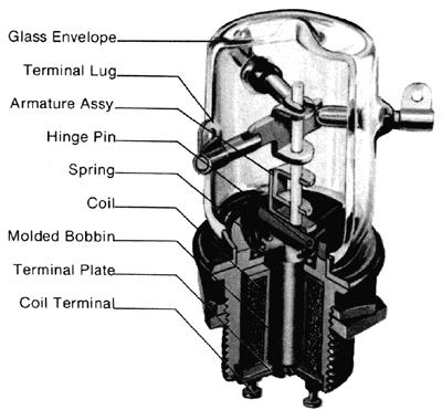
High voltage relay construction.
Image credit: TE Connectivity
Specifications
Performance Specifications
Buyers of high voltage relays should pay special attention to the product's performance specifications, including maximum voltage and dielectric strength.
A relay's maximum switching voltage simply refers to the amount of voltage the product can withstand without physical damage. Likewise, a product's maximum current refers to maximum continuous current allowable across the output terminals under specified environmental conditions. Maximum current is sometimes known as maximum switching current.
Dielectric strength is also known as isolation voltage and is defined as the maximum potential gradient an insulating material can withstand without physical damage. This spec is expressed in the volts (V) or kilovolts (kV) the material can handle before breakdown.
Switch Specifications
The GlobalSpec — Industrial Products and Supplies database contains information about a high voltage relay's switch, including the number of poles and throws.
The term pole describes the number of separate circuits controlled by a switch. The number of circuits controlled by the relay determines the number of switch contacts, which in turn determines the poles needed to make or break the contacts. Switches typically have between one and four poles.
The image series below illustrates, from left to right, a single pole (SP), double pole (DP), and triple pole switch (3P). Note that, in the last image, the switch is connected to three separate circuits and has three contacts.

Image credit: Enasco | Skycraft Surplus | Frank Alapini
A throw defines the number of distinct positions a switch is capable of. It is important for a relay switch's throws to suit its application.
Single throw (ST) switches are open in one position and closed in another. For example, a single pole single throw (SPST) switch is a simple on-off switch, such as a light switch. A double pole single throw (DPST) switch is an on-off switch that opens and closes two contacts with a single motion.
Double throw (DT) switches are two-way devices. Double throw relays have three contacts and two positions: in the first position, Contacts 1 and 2 are in contact, but the third remains open. In the second position, this connection is reversed to Contacts 2 and 3.
Specifications about contacts, including contact orientation and maximum ratings, are important to consider when selecting electromechanical relays.
Contact orientation refers to the switch's position when a relay coil is not energized. As its name implies, a normally open (NO) switch is open in a resting, non-energized position; when current is passed through the relay, the switch then closes. A normally closed (NC) switch is therefore reversed: closed at rest, and open when energized. Changeover switches contain both NO and NC contact types.
Contacts are frequently rated to accept a maximum amount of current allowable under specified heat dissipation and ambient conditions. Maximum current is sometimes referred to as maximum switching voltage (expressed in volts) or maximum switching current.
The speed specifications of a relay includes make time and break time. Make time refers to the amount of time a switch needs to operate and make contact, while break time is the amount of time required to release and break contact. Switch speed is typically measured and specified in milliseconds. Higher speed devices have several advantages over lower speed ones. In high voltage applications fast switching reduces arcing and the possibility of physical damage.
Mounting
High voltage relays may be mounted using a number of different methods.
- Bracket (or flange) mounted relays are equipped with a flange for mounting. The flange is typically installed by bolting the device to a matching flange which is then welded to a corresponding wall.
- DIN rail mounted devices are equipped with fasteners capable of mounting on DIN rails. DIN rails are mounting devices standardized by the Deutsches Institut fur Normung (DIN).
- Panel mount relays are manufactured for mounting to an electrical panel.
- PCB relays are mounted on printed circuit boards (PCB) using through hole contacts or surface mount technology (SMT).
- Socket relays are mounted to PCBs using pin sockets.
Isolation
High voltage relays may use one of several different methods to isolate the contacts. As mentioned above, the product may use a vacuum as an isolation method and also to prevent arcing. Other relays may use air or a gas mixture as the dielectric isolation material. Reed switches are also used for isolation and can switch devices such as solenoids, contactors, and motors.
High Voltage Relays FAQs
How do high voltage relays differ from standard relays in terms of design and functionality?
The following design characteristics apply to high voltage relays:
Dielectric Material: They often use vacuum or gas as the dielectric material. Vacuum has a dielectric strength about eight times greater than air, which allows these relays to handle higher voltages without arcing. This is a significant design difference from standard relays, which typically use air as the dielectric.
Contact Materials: May use harder contact materials such as molybdenum and tungsten to accommodate larger loads and prevent wear, which is not typically necessary in standard relays.
Voltage and Current Handling: Are designed to withstand higher voltages and currents. They are heavily insulated and can handle multiple kilovolt (kV) surges, unlike standard relays which are designed for lower voltage applications.
Isolation and Dielectric Strength: Have a higher dielectric strength, meaning they can withstand greater potential gradients without physical damage. This is a critical design feature for applications involving high voltages.
Applications: Used in applications that require switching of larger loads and high in-rush currents, such as in ESD test equipment, cable test equipment, and heart defibrillators. These applications benefit from the high voltage relay's ability to handle high voltages and currents safely.
What are the typical materials used in the construction of high voltage relays?
Dielectric Materials
Vacuum: Vacuum is often used as a dielectric material in high voltage relays because it has a dielectric strength about eight times greater than air. This allows the relay to handle higher voltages without arcing.
Gas: Various gases can also be used as dielectric materials. These gases help in preventing arcing and are suitable for applications requiring high in-rush currents. Sulfur Hexafluoride and Nitrogen both have desirable characteristics as a back-fill gas.
Contact Materials
Copper: Low resistance copper contacts are used in vacuum environments, allowing the relay to carry significantly more current than traditional open-air relays.
Molybdenum and Tungsten: These harder contact materials are used to accommodate larger loads and more wear resistant, which is essential for high voltage applications.
How do the contact materials affect the performance of high voltage relays?
Current Carrying Capacity
Copper Contacts: In vacuum environments, low resistance copper contacts are used, which allow the relay to carry significantly more current than traditional open-air relays. This is because there is no oxidation in a vacuum, which helps maintain low resistance and high conductivity.
Durability and Load Handling
Molybdenum and Tungsten Contacts: These harder contact materials are used to accommodate larger loads and help prevent wear. This is essential for high voltage applications where the relay needs to handle high in-rush currents and large electrical loads without degrading quickly.
Arcing Prevention
The choice of contact materials, along with the dielectric environment (such as vacuum or gas), helps prevent arcing. This is important in high voltage applications to ensure reliable operation and longevity of the relay.
What are the advantages of using vacuum as a dielectric material in relays?
High Dielectric Strength
Vacuum has a dielectric strength approximately eight times greater than air, which allows relays to handle higher voltages without arcing. This makes vacuum an excellent choice for applications requiring high voltage isolation and reliability.
Reduced Oxidation
In a vacuum environment, there is no oxidation, which helps maintain low resistance and high conductivity in the relay contacts. This is particularly beneficial for copper contacts, allowing them to carry significantly more current than they would in open-air environments.
Improved Performance in Harsh Environments
Vacuum relays are designed to operate effectively at various altitudes and in harsh environments, making them suitable for a wide range of applications, including high power RF circuits.
Compact Design
The use of vacuum as a dielectric allows for smaller relay designs while maintaining good dielectric isolation at rated voltages. This compactness is advantageous in applications where space is a constraint.
How does the dielectric strength of vacuum compare to other materials used in relays?
Vacuum Dielectric Strength
The dielectric strength of vacuum compared to other materials used in relays is eight times greater than air.:
Comparison with materials other than vacuum
Gas: Various gases are also used as dielectric materials in high voltage relays. While gases can prevent arcing and are suitable for high in-rush current applications, the dielectric strength of vacuum is generally higher, providing better isolation and performance in high voltage scenarios.
What are the challenges in designing high voltage relays?
Dielectric Material Selection
Choosing the appropriate dielectric material is crucial. Vacuum and gas are commonly used due to their high dielectric strength, but each has its own design considerations. Vacuum is beneficial for preventing arcing.
Contact Material and Design
The contact materials, such as copper, molybdenum, and tungsten, must be selected to handle large loads and reduce wear. These materials need to maintain low resistance and high conductivity, especially in vacuum environments where oxidation is not a concern.
Load Handling and Switching Capability
High voltage relays must be designed to switch larger loads and handle high in-rush currents. This requires careful consideration of the relay's load switching capability and the use of harder contact materials to accommodate these demands.
Size and Compactness
Designing relays that are compact yet capable of handling high voltages is a challenge. Vacuum relays, for instance, are designed to be small while maintaining good dielectric isolation at rated voltages.
Environmental Considerations
High voltage relays must be able to operate effectively in various altitudes and harsh environments. This requires robust design to ensure reliability and performance under different environmental conditions.
High Voltage Relays Media Gallery
References
Electronics360—The Role of the Relay Switch in Circuit Design
GlobalSpec—Electromechanical Relays
National Instruments — How to Choose the Right Relay
- 220 volt relays
- 24 volt relays
- 400Hz relay
- 5 volt relays
- high voltage relays PCB
- 1.5 volt relays
- 100 amp 240 volt relays
- 2 volt relays
- 230 volt relays
- 3 volt relays
- 3.3 volt relays
- 36 volt relays
- 9 volt relays
- line voltage relays
- miniature high power relays
- reverse power relays
- solid state power relays
- ultra low power relays
- variable voltage relays
- wetting voltage relays
- zero voltage relays