Shift Registers Information
Last revised: October 5, 2024
Reviewed by: Scott Orlosky, consulting engineer
 Shift registers are logic circuits that are used to sequentially store and move data. They accept binary inputs from one serial or parallel source and then shift the data through a chain of flip-flops, one bit at a time.
Types of Shift Registers
Shift registers are some of the most active chips in a computer. Although their basic function is to hold and transfer data, it must do that job flawlessly. Even one bit out of place can create an error in execution. Here are several ways in which shift registers can be used.
- Serial in/serial out (SISO) registers receive serial data from one input and send serial data from one output.
- Parallel in/serial out (PISO) registers receive parallel data from several inputs and send serial data from one output.
- Serial in/parallel out (SIPO) registers receive serial data from one input and send parallel data from several outputs.
- Parallel in/parallel out (PIPO) registers receive parallel data from several inputs and send parallel data from several outputs.
- Universal shift registers have selectable inputs that allow users to set the register to operate as a SISO, PISO, SIPO, or PIPO device.
- Shift right registers move the register data to the right so that each operation successively divides the binary number by two.
- Shift left registers move the register data to the left so that each operation successively multiplies the binary number by two.
- Bidirectional or reversible registers that can shift data to either the left or the right are also available.
Performance Specifications
 Selecting shift registers requires an analysis of performance specifications.
The number of bits is the maximum number of bits that a register can store at one time.
- The clock frequency is the highest rate in hertz (Hz) at which the shift register can shift data reliably.
- Propagation delay is the time delay between the occurrence of a change at the output and the application of a change at the inputs.
- Operating current and operating temperature are other important considerations.
- Power dissipation, the device's total power consumption, is generally expressed in watts (W) or milliwatts (mW).
- Supply voltages range from - 5 V to 5 V and include many intermediate voltages.
Output Characteristics
Shift registers vary in terms of output characteristics and optional features.
- Open-collector outputs are connected internally to the collector for a bipolar transistor.
- Open-drain outputs are connected internally to the drain for a field effect transistor. (or FET)
- Devices with three-state output buffers are also available.
In terms of features, some shift registers are radiation tolerant or provide protection from electrostatic discharge (ESD). Others have buffered inputs or synchronous or asynchronous resets. Variable length registers that can be programmed to any number of bits between 1 and a maximum value are commonly available.
Logic Families
 Selecting shift registers requires an analysis of logic families.
- Transistor-transistor logic (TTL) and related technologies such as Fairchild advanced Schottky TTL (FAST) use transistors as digital switches. By preventing saturation, it speeds up the time to switch off.
- By contrast, emitter coupled logic (ECL) uses transistors to steer current through gates that compute logical functions.
- Another logic family, complementary metal-oxide semiconductor (CMOS), uses a combination of p-type and n-type metal-oxide-semiconductor field effect transistors (MOSFETs) to implement logic gates and other digital circuits.
- Other logic families for shift registers include cross-bar switch technology (CBT), gallium arsenide (GaAs), integrated injection logic (I2L), and Gunning with transceiver logic (GTL).
Standards
- JEDEC JEB 19 — Recommended Characterization Of Mos Shift Registers
- Mil-M-38510/665 — Microcircuits, Digital, High Speed, CMOS, Shift Register, Monolithic Silicon
- SMD 5962-96558 — Microcircuit, Digital, Advanced CMOS, Radiation Hardened, 8-Bit Serial / Parallel-In, Serial-Out Shift Register, Monolithic Silicon
Shift Registers FAQs
How do different logic families impact the performance of shift registers?
The performance of shift registers can be significantly impacted by the choice of logic families.
Transistor-Transistor Logic (TTL) and FAST TTL
TTL and its variant FAST TTL are known for their relatively high speed. FAST TTL, in particular, offers faster switching times due to the use of Schottky diodes to reduce transistor saturation. TTL circuits generally consume more power compared to CMOS circuits. TTL circuits have moderate noise immunity.
Emitter Coupled Logic (ECL)
ECL is one of the fastest logic families because it avoids transistor saturation by steering current through gates. ECL consumes more power than TTL and CMOS because it continuously draws current. ECL has excellent noise immunity due to its differential nature.
Complementary Metal-Oxide-Semiconductor (CMOS)
CMOS technology has improved significantly over the years, offering competitive speeds, though traditionally it was slower than TTL and ECL. CMOS is known for its low power consumption, especially in static conditions where it consumes almost no power. CMOS circuits have high noise immunity.
Other Logic Families
Cross-Bar Switch Technology (CBT), Gallium Arsenide (GaAs), Integrated Injection Logic (I2L), and Silicon on Sapphire (SOS): These specialized logic families offer various trade-offs in terms of speed, power consumption, and noise immunity. For example, GaAs is known for high-speed performance but is more expensive and consumes more power.
Gunning Transceiver Logic (GTL) and GTLP: These are optimized for high-speed data transmission with low power consumption and are often used in bus interfaces.
What is the impact of temperature on noise immunity in different logic families?
The impact of temperature on noise immunity in different logic families is an important consideration in digital circuit design.
The noise immunity of a logic family is characterized by its input low voltage (V_IL) and input high voltage (V_IH) thresholds. These thresholds can vary with temperature, which means that the ability of a logic circuit to distinguish between a logic "0" and a logic "1" can be affected by temperature changes.
The supply voltage can also influence noise immunity, and this effect can be exacerbated by temperature variations. If all ICs are fed from the same supply, this is less of an issue, but it becomes significant when interfacing logic circuits with different supply rails.
Transistor-Transistor Logic (TTL) and FAST TTL
TTL circuits have moderate noise immunity, and their performance can be affected by temperature variations. The thresholds for V_IL and V_IH may shift with temperature, potentially reducing noise immunity.
Emitter Coupled Logic (ECL)
ECL circuits have excellent noise immunity due to their differential nature. However, ECL is also sensitive to temperature changes, which can affect the current-steering mechanism and, consequently, the noise margins.
Complementary Metal-Oxide-Semiconductor (CMOS)
CMOS circuits have high noise immunity, but their performance can still be influenced by temperature. The V_IL and V_IH thresholds in CMOS can vary with temperature, impacting the noise margins.
Other Logic Families:
Gallium Arsenide (GaAs), Cross-Bar Switch Technology (CBT), Integrated Injection Logic (I2L), and Silicon on Sapphire (SOS): These specialized logic families have varying levels of noise immunity, and their performance can also be affected by temperature changes. For example, GaAs is known for high-speed performance but may have different noise immunity characteristics compared to CMOS or ECL, especially under temperature variations.
The worst-case values of V_IL and V_IH for each logic family can be found on data sheets, and these values may vary with temperature. It is crucial to ensure that the values used in design are guaranteed across the device's temperature range.
Temperature Range: When designing with logic ICs, it is important to consider the operating temperature range of the components and ensure that the noise immunity is maintained within this range.
What is the impact of clock frequency on the performance of shift registers?
The impact of clock frequency on the performance of shift registers is a critical aspect to consider in digital circuit design.
The clock frequency determines the rate at which data is shifted through the register. Higher clock frequencies allow for faster data transfer rates.
The maximum data rate of a shift register is directly proportional to the clock frequency. For example, if a shift register operates at a clock frequency of 10 MHz, it can shift data at a rate of 10 million bits per second.
Propagation delay is the time it takes for a signal to propagate through the shift register. Higher clock frequencies can exacerbate the effects of propagation delay, potentially leading to timing errors.
Setup and hold times are the minimum times before and after the clock edge that data must be stable. At higher clock frequencies, the setup and hold times become more critical, as there is less time for the data to stabilize.
Higher clock frequencies generally lead to increased power consumption. This is because the switching activity per unit of time within the shift register increases, leading to higher dynamic power dissipation.
At higher clock frequencies, issues such as signal integrity and noise become more pronounced. This can affect the reliability of the data being shifted through the register.
What is the impact of propagation delay on shift registers?
The impact of propagation delay on shift registers is a critical factor in their performance and reliability. Here are the key points to understand:
The maximum data rate of a shift register is influenced by its propagation delay. A longer propagation delay means that the shift register cannot operate at higher clock frequencies, thereby limiting the data rate.
the clock frequency determines the rate at which data is shifted through the register. Higher clock frequencies require shorter propagation delays to ensure reliable data transfer.
Propagation delay affects the setup and hold times of a shift register. These are the minimum times before and after the clock edge that data must be stable. If the propagation delay is too long, it can cause timing issues, leading to data corruption.
In systems with multiple shift registers, differences in propagation delay can lead to clock skew, where different parts of the system are not synchronized properly.
While propagation delay itself does not directly impact power consumption, the need to operate at higher clock frequencies to achieve faster data rates can lead to increased power consumption. This is because higher clock frequencies result in more frequent switching activity within the shift register.
Longer propagation delays can exacerbate issues related to signal integrity, such as reflections and crosstalk. This can affect the reliability of the data being shifted through the register.
As propagation delay increases, the shift register may become more susceptible to noise, especially at higher clock frequencies. This can impact the overall performance and reliability of the shift register.
Propagation delay can be affected by temperature variations. Higher temperatures can increase the propagation delay, which in turn can impact the timing and performance of the shift register. This is particularly important in environments with significant temperature fluctuations.
What are good design practices for shift registers?
To minimize interference and noise, use proper shielding to reduce electromagnetic interference. Add decoupling capacitors near the power supply pins of the shift register to filter out noise. Using twisted pair cables for data lines will reduce electromagnetic interference. And be sure to keep high-frequency lines away from the shift register to prevent cross-talk.
Shift Registers Media Gallery
References
GlobalSpec: Circuit Design: Know It All
Image Credit
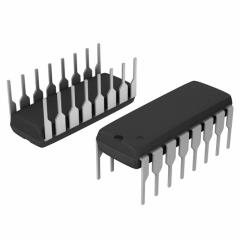
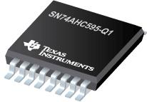
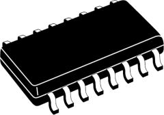
Digi-Key Corporation | Texas Instruments | RS Components, Ltd.
- -3.3 V
- 1.2 V
- 1.5 V
- 1.8 V
- 2.5 V
- 3 V
- 3-State Output
- 3.3 V
- 3.6 V
- 5 V
- Advanced CMOS
- BGA
- Bidirectional
- CDIP
- DIP
- ESD Protection
- Emitter Coupled Logic (ECL)
- Fast CMOS
- High-Speed CMOS
- LCCC
- Low Voltage CMOS
- Open-collector Output
- Open-drain Output
- PDIP
- PLCC
- Parallel In / Parallel Out
- Parallel In / Serial Out
- QFP
- SOIC
- SOP
- SSOP
- SZIP
- Serial In / Parallel Out
- Serial In / Serial Out
- Shift Right
- Standard CMOS / CMOS 4000
- TSSOP
- TVSOP
- Transistor-Transistor Logic (TTL)
- Universal Shift Register
- PISO shift register VHDL code
- 16 bit SIPO shift register
- 74194 4-bit bidirectional universal shift register
- 8 bit PIPO shift register
- 10 bit shift registers
- 12 bit shift registers
- 16 bit universal shift registers
- 24 bit shift registers
- 3 bit ring counters
- 3 bit shift registers
- 32 bit shift registers
- 5 bit ring counters
- 5 stage twisted ring counters
- I2C shift registers
- multiple input shift registers
- VHDL 16 bit shift registers