The Verilog Hardware Description Language, Fifth Edition

A valuable resource for engineers and students interested in modeling digital systems, this book takes a tutorial approach to presenting the major features of the language and its constructs.
We have seen how to specify combinational logic and sequential elements to a synthesis tool. In this section we will combine these into the specification of a finite state machine. The standard form of a finite state machine is shown in Figure 2.1. The machine has inputs x i, outputs z i and flip flops Q i holding the current state. The outputs can either be a function solely of the current state, in which case this is a Moore machine. Or, they can be a function of the current state and input, in which case this is a Mealy machine. The input to the flip flops is the next state; this is a combinational function of the current state and inputs.
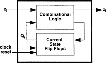
The Verilog description of a finite state machine (FSM) follows this model closely. The outer box of Figure 2.1 will be the FSM module. The two inner boxes will be two separate always statements. One will describe the combinational logic functions of the next state and output. The other will describe the state register.
An example of an FSM description will be presented using the explicit style of FSM description. In this style, a case statement is used to specify the actions in each of the machine's states and the transitions between states. Consider the state transition diagram shown in Figure 2.2.