Recall from Section 7.5 in Chapter 7 on the "Frequency Sampling Design Method":
| (E.1) | 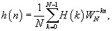
|
where h( n), 0 ? n ? N ? 1, is the causal impulse response that approximates the finite impulse response (FIR) filter, and H( k), 0 ? k ? N ? 1, represents the corresponding coefficients of the discrete Fourier transform (DFT), and W N =  . We further write DFT coefficients H( k), 0 ? k ? N ? 1, into the polar form:
| (E.2) | 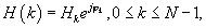
|
where H k and ? k are the kth magnitude and the phase angle, respectively. The frequency response of the FIR filter is expressed as
| (E.3) | 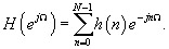
|
Substituting (E.1) into (E.3) yields
| (E.4) | 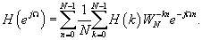
|
Interchanging the order of the summation in Equation (E.4) leads to
| (E.5) | 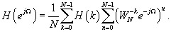
|
Since 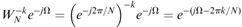 ,
,
and using the identity 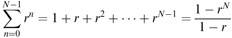 ,
,
we can write the second summation in Equation (E.5) as
| (E.6) | 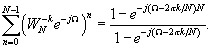
|
Using the Euler formula leads Equation (E.6) to
| (E.7) | 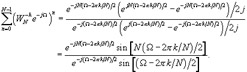
|
Substituting Equation (E.7) into Equation (E.5) leads to
| (E.8) | 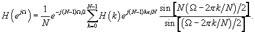
|
Let ? = ? m =  , and substituting it into Equation (E.8) we get
| (E.9) | 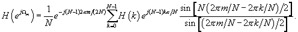
|
Clearly, when m ? k, the last term of the summation in Equation (E.9) becomes
When m = k, and using L'Hospital's rule, we have
Then Equation (E.9) is simplified to
| (E.10) | 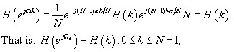
|
where ? k =  , corresponding to the kth DFT frequency component. The fact is that if we specify the desired frequency response,
Copyright Elsevier Inc. 2008 under license agreement with Books24x7