
Rotary Position Sensors Information
 Rotary position sensors provide electrical outputs relative to shaft rotation in order to precisely measure angles. These devices are used in multiple position sensing applications, including:
-
gear position
-
automotive position sensing, including throttle position, steering wheel position, and pedal position
-
industrial control
-
valve control
-
HVAC damper control
Rotary position sensors are similar to rotary encoders, but differ in that rotary encoders are used to measure a number of completed turns of a shaft, whereas rotary position sensors are used to measure the angle of an incomplete turn.
Types of Rotary Position Sensors
Rotary Potentiometers
Rotary potentiometers consist of a circular conductive track and an electrical wiper attached to a central shaft. A constant voltage is applied to the track; as the shaft turns and the wiper contacts the track, the output voltage varies proportionally to the shaft angle. In this way rotary potentiometers are technically specialized voltage dividers. These devices typically offer 360° shaft rotation and can measure angle over the majority of this rotation.
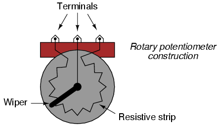
Image credit: Learning Electronics
Hall Effect Sensors
Hall effect sensors rely on a conductor's voltage difference relative to a magnetic field (also known as the Hall effect) to output angle position. These sensors typically consist of a Hall element, a rotating shaft, and a magnet. When the angular position of the element changes, the corresponding changes in the magnetic field results in a linear change in output voltage.
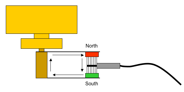
A Hall effect sensor relative to a rotating shaft. Image credit: B. Mumford
Hall effect sensors are better suited to harsh environments because, unlike potentiometers, they do not rely on direct electrical contact due to their use of a magnetic field. Disadvantages of using Hall effect sensors include potential interference from nearby wires or other magnets.
Variable inductance sensors are similar to Hall effect devices in that they utilize a magnetic field in conjunction with multiple stationary coils. By resolving the imbalance present between the coils, the sensor detects and outputs angular position.
Resolvers
Resolvers contain three coils: a rotating coil (or rotor) and two stationary coils (or stators) situated 90° apart. Current is passed through the two stationary coils; by comparing these two currents in relation to the rotating coil, the resolver can precisely detect the shaft position. Like Hall effect and variable inductance sensors, resolvers rely on magnetic fields and are subject to the advantages and disadvantages of other magnetic sensors.
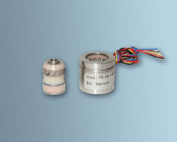
A resolver, with rotor removed. Image credit: LTN
Synchros are essentially resolvers with four total coils, including three stationary coils spaced 120° apart.
Specifications
When selecting rotary position sensors, it is important to consider measurement specifications such as maximum angle, mechanical range, and accuracy.
Maximum angle simply refers to the greatest angle that the sensor can measure. For example, a device's shaft may be able to rotate a full turn (or 360°), but the device's maximum angle might be only 348 or 350°, leaving 10° of immeasurable shaft rotation. When selecting rotary position sensors, buyers should specify maximum angle as the desired range of measurable angles (ie 20 to 340°, and should specify mechanical range as the single value maximum of measurable angle (ie 350°).
Accuracy refers to the device's ability to accurately output readings and is expressed in positive/negative percentage of full scale. Buyers should select products with low accuracy percentages to maximize sensor efficiency.
Rotary position sensors may use one of several types of electrical outputs in order to relay position data.
Analog current may be imposed on the output circuit relative to the angular position. Devices that output analog current are useful for sending long distance signals, and are sometimes called transmitters. Analog current output is typically expressed as a range, such as 0-20 mA.
Analog voltage is a continuous linear function of the device output. Like analog current, it is sometimes expressed as a voltage range.
Analog frequency outputs are encoded via some type of modulation scheme, such as amplitude modulation (AM) or frequency modulation (FM). Examples include waveforms such as sine waves and square waves.
Resistance output is measured in ohms (Ω)
Digital outputs include serial and parallel signals. Serial signals are transmitted one bit at a time and are represented by standards such as RS-232, RS-422, and RS-485. By contrast, parallel communication involves sending many bits of information at once.
References
McLaren Electronic Systems - Rotary Position Sensors
Image credit:
Spectrum Control and Sensors
- tamagawa resolver
- rotary resolver
- steering angle sensor
- 4 bit absolute encoder
- angular magnetic encoder chip
- angular position resolver
- brushless resolver
- danaher resolver
- rotary angle decoder
- rotational speed measurement
- sine cosine resolver
- synchro resolver
- automotive rotary position sensors
- dual output rotary position sensors