Low Power Methodology Manual: For System-on-Chip Design
Taking a practical approach, rather than a theoretical approach, this book describes a number of the techniques designers can use to reduce the power consumption of complex SoC designs.
The SALT technology demonstrator project provided a platform for testing the approaches to power gating and state retention described in this book. In this chapter we give some more details on the system design and RTL coding for this project.
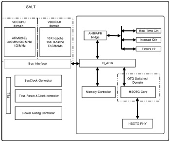
The SALT chip is implemented in 90nm generic technology and contains an ARM processor, an AMBA bus and set of peripherals, and a Synopsys USB OTG digital core and PHY. The ARM core and the USB core are independently power gated. The ARM core uses full state retention; the USB uses partial state retention. Both the ARM core and the USB use switching fabrics of header switches; thus they switch VDD and use a common ground (VSS).
In this first section, we describe the power gating design for the processor. Figure 7-1 on page 86 shows a simplified block diagram of the SALT chip.
Most battery-powered processor based designs have to deal carefully with the balance between performance (to support product features) and low power (to support long battery life). The performance requirement steered us to a higher performance, leakier process. To maintain long battery life, we needed to provide aggressive leakage management.
For the SALT project, the processor uses four low-power modes. In all modes, the power controller generates a SLEEP signal to enter the low power mode and the WAKE signal to exit. In order of increasing leakage savings and increasing time to power up...