Antennas Information
Antennas are mechanical components which either transmit or receive radio frequency signals. For transmission, an oscillating RF electrical current is fed to the antenna's terminals, where the conduit radiates the signal as electromagnetic waves. For reception, an antenna captures some of the original signal to produce a voltage upon its terminals which is then amplified. Antennas are used in every instance of RF communication, including radio and TV broadcasts, handheld transceivers, cell phones, radar systems, satellite communications, Wi-Fi networks, and remote controls.
Radio frequencies transmit audio, video, or data via electromagnetic waves produced by a variable voltage or alternating current applied to an antenna. Atoms excited by this charge have one or more weakly-held electrons in their outer shells and these can transition from atom to atom. The slight motion of electrons along the antenna is enough to cause electromagnetic waves to pulse at the same frequency as the charge applied to the antenna. The rate of oscillation is known as frequency and is measured in hertz, and RF is transmitted between 3Hz to 300THz.
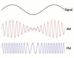
In order to encode information within the wave, an operator needs to modulate the wave accordingly.
- Pulse modulation is achieved by turning the RF on and off. It is obsolescent, and only sufficient for Morse code.
- Amplitude modulation changes the amplitude of the RF wave (it's peak-to-peak voltage) to encrypt the signal with audio or visual information.
- Frequency modulation is the most common type of RF encoding, and changes the frequency of the sine wave to convey information in the signal.
- Phase modulation is a method that uses changes in the phase of the carrier wave to encode information.
- Sideband modulation is a variation of amplitude modulation that requires less bandwidth and power and does not use a carrier wave. It is often used for long distance communications.
Other methods of modulation exist, especially in digital communication applications, but they are based on the aforementioned methods.
An antenna is also utilized to receive electromagnetic waves, but in this case to divine the signal from the environment. The antenna's metal construction conducts enough RF waves that a tuner must be able to isolate the signal indicated by the operator. Just as the excited electrons transmit oscillating electromagnetic waves, electrons in the reception antenna receive them. The number designations provided by a tuner is representative of the hertz of the RF signal. Tuners demodulate the signal by interpreting the amplitude, frequency, or phase of the wave. A transistor amplifies the signal for auditory, visual, or data output.
There are essentially two types of antenna constructions: omnidirectional and directional. Omnidirectional antennas radiate RF uniformly in all directions, with the power decreasing at elevations above or below the plane to reduce power waste and increase transmission distance. Directional antennas are designed to propagate radio waves in a specific direction with a high concentration of focus. These are excellent for direct communication between two points. In reality, no antenna is completely directional or omnidirectional, but such terminology distinguishes how the signal is applied.
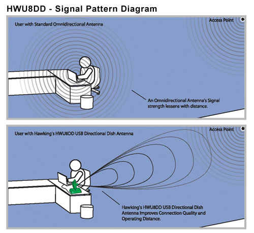
Omnidirectional and directional antennas represented in WiFi
Types of Antennas
Antenna configurations to increase directionality include:
| Yagi-Uda antennas, which have an active element with accompanying parasitic and reflective elements to create a highly-directed transmission. |
|
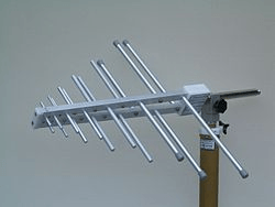
| Log-periodic antennas, which are multi-element, unidirectional, narrow-beam antennas that have impedance and radiation characteristics that are regularly repetitive as a logarithmic function of the excitation frequency. The length and spacing of the elements of log periodic antennas increase logarithmically from one end to the other. Log periodic antennas are often utilized in broadband applications. |
|
| Parabolic reflectors, or dish antennas, consist of reflector backed arrays. An active element in the focal point of the array radiates or receives signals that bounce off the reflector. The reflector may consist of a solid dish, open grid, or a plane. Several variations exist such as corner, parabolic, dish, plane or patch, front fed parabolic, Cassegrain (rear fed parabolic), and spherical reflectors. |
Image credit: DirecTV |
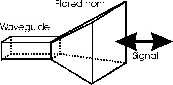
| Horn antennas feature tapered waveguides to direct RF with a beam. They are most common for directing frequencies above 300 MHz. |
|
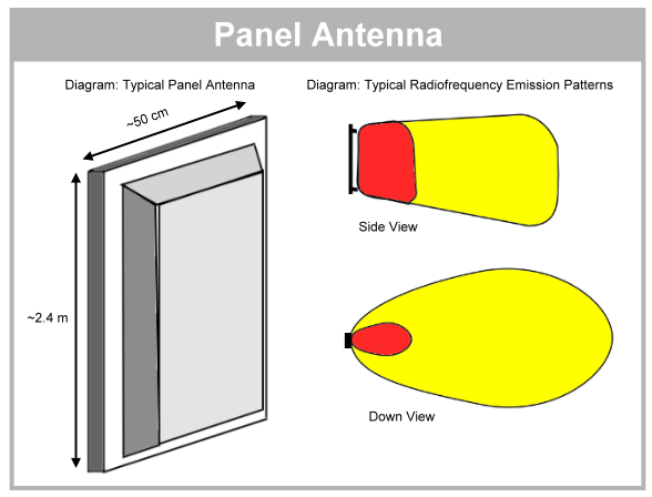
| Panel antennas (and sector antennas) usually have a flat panel shape and are enclosed within a plastic radome to protect the elements and electronics. These use a microstrip-patch or planar array antenna or multiple dipoles. The cell site can use several panel antennas or bays of panels as required, and adaptive antennas can select the optimal antenna for the application. They are most often used in broadcasting. |
|
Other types of antennas can be adjusted to transmit directionally:
| Helical antennas feature a conductor wound in the shape of a helix. By alternating the operating mode (from broadside to end-fire) of the antenna it can be omnidirectional or directional. Helical antennas propagate circularly polarized signals which are better explained in the 'Polarization' section below. |
|
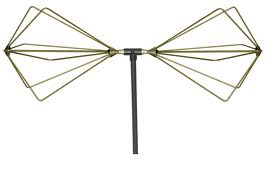
| Biconical antennas are a specialized type of antenna consisting of two conical conductors, having a common axis and vertex, and extending in opposite directions with feed or excitation through the vertex. When one of the cones is reduced to a plane, the antenna is called a discone. Biconical antennas are also known as bicone or bowtie antennas. |
|
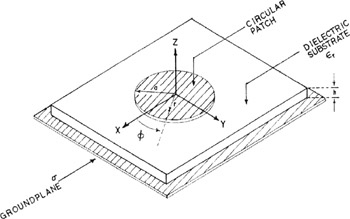
| Microstrip antennas have low efficiency, are easily fabricated with printed circuit board techniques,and can be made to conform to most surface profiles. They can have an unlimited number of shapes and sizes, but can transmit/receive in almost any polarization. These antennas have moderate inherent directivity, but arrays can be better tuned for specific directions. |
|
| Loop antennas have radiation patterns that are omnidirectional, and a small antenna with a circumference of 1/10th or less the wavelength of the transmission are mostly suitable only as receiving antennas. However, larger loop antennas (a circumference at least equal to, or an odd multiple of, the wavelength) can be used to achieve some gain because the signal is radiated across the plane of the loop. Including loop antennas in an array or as part of Yagi configuration will further increase directivity. |
|
Omnidirectional antennas feature no design alterations to affect the direction of a signal.
|
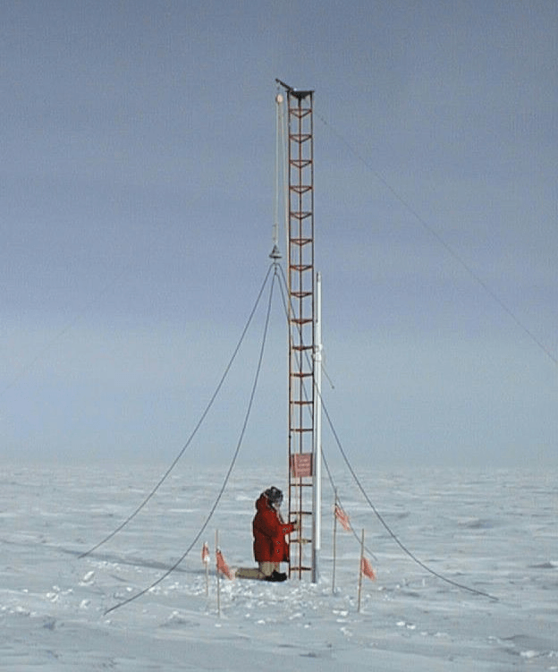
Monopole antennas (also known as whip or vertical antennas), which consist of a rod-shaped conductor that has one end attached to a ground, often the Earth. The signal is applied by the lower end of the antenna. |
|
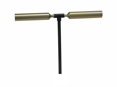
| Dipole antennas, which consist of two balanced terminals with equal but opposite voltage, and the signal is applied across the antenna halves. |
|
Array Directivity
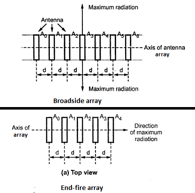
Furthermore, it becomes possible to adjust the directional capabilities of an array by making the array a broadside array or end-fire array. In broadfire arrays, all antenna elements are placed parallel to each other along an axis, and radiation is maximized along the direction in which the elements point. End-fire arrays require the elements to share an axis as well, but RF radiation is maximized along the axis direction instead.
Antenna Parameters
Congruent to the reciprocity theorem, the characteristics which define RF transmissions -- which follow below -- must be mutually supported by the transmitting and receiving antennas. For this reason, it is often unnecessary to distinguish between the transmitting and receiving antennas.
Gain
The term gain can be somewhat misleading, because an antenna is a passive component and it does not amplify anything. Gain is the ratio of the maximum power density of a directional antenna at a specific distance, in contrast to the power density of omnidirectional antenna (assumed to be operating at 100% efficiency, though it is impossible) when both antennas are supplied identical charge. An omnidirectional antenna with equal radiation in every direction has 0 decibels (dB). The decibel is a unit of measurement which quantifies power or intensity in relation to a known reference. In this instance, it is the quantity of RF produced by the antenna.
Fields
Explore Gate's Yuval Tsur explains the differences between far fields, near fields, and Frennel zones and how electromagnetic waves behave in each classification.
Efficiency
Efficiency is a measure of how well the antenna converts a supplied charge into radiated power. Due to the physical limitations of antennas, it is virtually impossible to achieve 100% efficiency. Voltage standing wave ratio (VSWR), the amount of power that is transmitted but then reflected back to the source, is due to impedance mismatching between conduits. There are other sources of inefficiency:
- Dielectric loss is the heat generated by imperfections in the insulating materials.
- Ohmic loss accounts for the resistance of the antenna material.
- Aperture loss accounts for poor field distribution across the antenna.
- Polarization loss occurs when an antenna transmits RF in an undesired polarization, which is further covered below.
- Space loss occurs as the electromagnetic waves have a larger area to cover as they radiate further from the antenna.
The efficiency of an antenna is frequently presented as a percent or in decibels. By matching the impedance of the materials which transmit the charge and resulting electromagnetic wave (radio, feedline, antenna), a minimal amount of energy is reflected back to the source, resulting in optimal charge to transmission efficiency. The amount of energy that a receiving antenna harnesses, once all losses and sources of impedance are accounted for, is known as the antenna aperture.
Bandwidth
Bandwidth is the range over which the antenna can transmit/receive radio. Broadcasts are entitled to a range of specific frequencies and the difference between the high and low is the bandwidth. An antenna transmitting between 20MHz and 40 MHz would have a bandwidth of 20 MHz. Manufacturers also supply an antenna's VSWR so users can determine any operating loses.
Polarization
The direction of the electrical part of the electromagnetic wave determines the wave's orientation. When antennas are mismatched, at least some of the signal is lost in what is called polarization loss. Therefore, a transmission is best-served by emitting and receiving antennas which have the same polarization. Polarizations include:
|
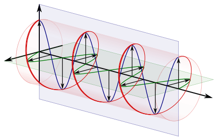
Circular polarizations have a plane of polarization that rotates in a circle, making one complete revolution during one period of the wave. A circular polarized wave radiates energy in both the horizontal and vertical planes and all planes in between. Circular polarization occurs where the horizontal and vertical components are equal but differ in phase by 90 degrees. Circular polarization is most often used on satellite communications. Elliptical polarization is a type of circular polarization but the difference, if any, between the maximum and the minimum peaks as the antenna is rotated through all angles, is called the axial ratio or ellipticity, and is usually specified in decibels (dB). If the axial ratio is near 0 dB, the antenna is said to be circular polarized. If the axial ratio is greater than 1-2 dB, the polarization is often referred to as elliptical. Right-hand-circular-polarization has a clockwise rotation when looking in the transmission direction. Left-hand-circular-polarization has a counterclockwise rotation when looking in the transmission direction. |
|
|
A linear polarized antenna radiates wholly in one plane containing the direction of propagation. A linearly polarized radio wave is composed of a single electric field component and a plot of the polarization pattern traced by the wave would be a straight line. It may be further characterized as horizontal linear or vertical linear. Dual polarization occurs where the horizontal and vertical polarization components are equal and in phase. Slant polarization is another form of linear polarization where the electric field lies in a plane at 45 degrees to the horizontal. Diversity polarization is where two antennas provide two separate orthogonal polarizations. An improvement in reception is obtained by combining the signals from the two elements. This type of polarization is useful for reception from hand held or mobile units where the orientation or polarization of the radio signals from the mobile transmitting antenna varies. |
Video Credit: ElectroScience Lab via YouTube |
Radiation Pattern
Manufacturers typically supply this information as a three- or two-dimensional graph. Power emitted by an omnidirectional antenna with 100 percent efficiency would be presented as a torus in a three-dimensional graph, and a circle on a two-dimensional graph. However, radio waves from the same antenna can interfere with each other and create amalgamated waves which are out of phase, effectively eliminating reception at some angles with respect to the antenna. Directional antennas are designed to have exceptional range in one direction, and when represented in a graphical format the 'lobes' (i.e. coverage) of an area becomes clear.
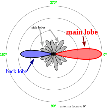
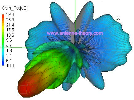
Directional antenna in a 2D graph (left) and a 3D graph (right)
Noise
Explore Gate offers a video explanation of antenna noise temperature.
Video credit: ExploreGate via YouTube
Antenna Placement
The accompanying table identifies common form factors for antennas.
| External | Antennas that are attached or located externally to the radio transmitter, receiver, transceiver, or waveguide. The unit may be freestanding on the ground or mounted on a mast, tower, portable hand radio, building, vehicle, or plane. |
|
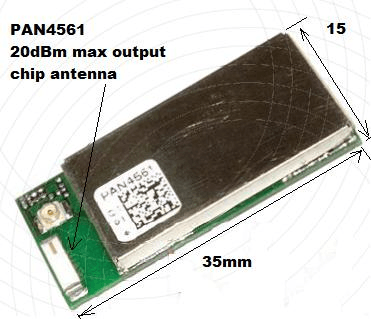
| Internal (Chip) | Internal antennas fit within the enclosure or case of the radio transmitter, receiver, transceiver or waveguide. For example, a microstrip antenna may be in the formed onto the surface of a plastic case or on the printed circuit board. Surface mount device (SMD) or "chip" antennas are mounted internally on the printed circuit board within the radio transmitter, receiver, or transceiver product. Chip antennas are also known as embedded antennas, integral antennas, chip dielectric antennas, or chip multilayer antennas. |
|
| Mobile | Antennas that are not stationary or fixed. Examples of portable or mobile antennas are antennas for hand held units, antennas mounted on vehicles, ships or planes and dish type antennas mounted on trailers | |
| Stationary |
Antennas designed for a fixed or stationary application such as a base station antenna or a satellite's Earth station antenna. |
|
| Collapsible | Antennas that slide or folds within the radio unit's case. Also, antennas that slide or fold into a more compact shape for transport or storage such as an antenna aboard a vehicle, ship, or spacecraft |
|
Features
These features may prove important when selecting antennas.
Lighting protection provides the antenna with a system to safeguard against lightning strikes. Inductivity between the transmitter and the antenna limits the voltage spike. A device on the transmitter monitors the voltage of the antenna and switches the transmitter off so long as the antenna remains dangerously charged.
A radome or dielectric coating provides circuit protection to sensitive antenna components. Though additional impedance is encountered by the signal, it can usually be overcome with design changes. Such measures ensure antenna up-time in poor weather and harsh environments. Panel and chip antennas frequently utilize some type of protective housing.
Applications
Antennas used for the propagation of radio waves are exceptionally common and nearly innumerable. Every modern vehicle -- automobiles, trains, boats and ships, aircraft, spacecraft-- relies on an antenna for either communications or entertainment. Militaries require more robust antenna designs which operate within a specified range of the electromagnetic wave spectrum. Cell phones and the networks in which they operate require a series of antennas for operation, and cell phone companies pay governments a licensing fee to broadcast data as RF. GPS relays RF between extraterrestrial satellites and handheld GPS units. WiFi, radar, Bluetooth, and RFID tags all utilize antennas. One of the most radical developments in antenna applications is wireless electricity, where antennas transmit RF at a high enough efficiency to supply an operating charge to the device. Though this technology has been around since 1891, it has yet to catch on.
Standards
Depending upon the antenna's end-use application, the following standards may be useful in considering antenna designs.
BS EN 60244 -- Measurement of all radio transmitters
ESDU 82031 -- Wind resistance of parabolic antennas
BS 6160 -- Radio equipment used in mobile services
CEA 2032 -- Indoor TV antenna performance
ITU-R F.1336 -- Radiation patterns of assorted antennas w/ frequencies between 1GHz and 70 GHz
ITU-R BT.419 -- Directivity and polarization of TV antennas
TIA TSB-171 -- History and analysis of terrestrial mobile radio systems
Resources
Bakshi, K.A.; Godse A.P.; Bakshi U.A.; Antenna & Wave Propogation. Retrieved June 2013 via Google Books
Wikipedia - Antenna (radio); Antenna measurement; Interference; Standing wave ratio;
Intuitor - The Physics of Resonance: How Antennas Work
Image credits:
Wikimedia Commons | Coolest Gadgets | PTub | Wikimedia Commons | DirecTV | Radio Electronics | Monash University| Wikimedia Commons | AH Systems | Engineering360 | Kr1st | Buzzle | AH Systems | Wikimedia | Electro Science Lab via YouTube | Nova Stanford | Texas Instruments | N7QVC | SVC Online
- Alabama
- Arkansas
- Arizona
- California
- Colorado
- Connecticut
- Florida
- Georgia
- Iowa
- Illinois
- Indiana
- Kansas
- Louisiana
- Massachusetts
- Maryland
- Maine
- Michigan
- Minnesota
- Missouri
- Mississippi
- Montana
- North Carolina
- New Hampshire
- New Jersey
- New Mexico
- Nevada
- New York
- Ohio
- Oklahoma
- Oregon
- Pennsylvania
- Rhode Island
- South Carolina
- South Dakota
- Tennessee
- Texas
- Utah
- Virginia
- Vermont
- Washington
- Wisconsin
- Aerospace / Military
- Air Traffic Control
- Array / Phased Array
- Biconical / Discone
- Broadband Network / WLAN
- Cellular / PCS Base Station
- Cellular / PCS Terminal
- Circular
- Coil / Helix
- Dipole / Wire Antenna
- Directional
- Dish / Reflector
- Dual Band / Multi-band
- External
- GPS
- High Frequency
- Horizontal Linear
- Horn / Aperture / Slot
- Internal / Chip
- Left Hand Circular (LHCP)
- Lightning Protection
- Linear
- Log Periodic Array
- Loop
- Marine / Shipboard
- Meets Military / Aerospace Specifications
- Microstrip
- Omnidirectional
- Panel / Sector
- Portable / Mobile
- RF Survey / Test
- RFID
- Radome / Dielectric Coating
- Retractable / Folding
- Right Hand Circular (RHCP)
- SMR / Trunking
- Satellite / Satcom
- Slant 45 / Dual
- Stationary / Fixed
- TV / Radio Broadcasting
- Telemetry / Surveillance
- Vehicular
- Vertical Linear
- Whip / Vertical Monopole
- Yagi or Yagi-Uda Array
- yagi antenna
- omnidirectional antenna
- xium antenna
- allgon antennas
- pdl 2 antenna
- UHF antenna
- hirschmann antenna
- HF antenna
- phased array antenna
- RF antenna switch
- beam antenna
- high gain antenna
- loop antenna
- microstrip antenna
- omni directional antenna
- patch antenna
- vertical dipole
- aircraft antenna
- bluetooth antenna
- broadband antenna
- dual band antenna
- GSM antenna
- parabolic antenna
- aircraft HF antenna
- biconical antenna
- maxrad antenna
- steerable antenna
- am antenna
- bowtie antenna
- microstrip patch antenna
