Time Delay Relays Information
Last revised: December 11, 2024
Reviewed by: Scott Orlosky, consulting engineer
Time delay relays and solid state timers use solid state electronic devices to provide a time delay. They may have displays, pots or other means of operator interface. They may also have electromechanical or solid state outputs.
The number of time ranges on relays and timers are single or multiple:
- Single time ranges may be fixed or programmable.
- Multiple time ranges can be programmed for multiple ranges.
A minimum and maximum time setting must also be specified. Some relays and timers have field selectable time ranges.
Time delay relays and solid state timers can have many timer functions or modes of operation which include:
Popular Types of Relays
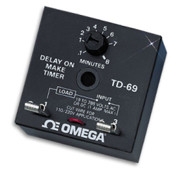
ON-Delay Timers
This type of timer can also be called:
- Delay on make
- Delay on operate
- Operate delay
- Prepurge delay
- Delay on energization
The time delay begins after application of power. At the end of the time delay the contacts open or close. If the contact is normally open (NO) the load energizes at the end of the time delay. If the contact is normally closed (NC) the load de-energizes after the time delay. Removing power resets the time delay and output.
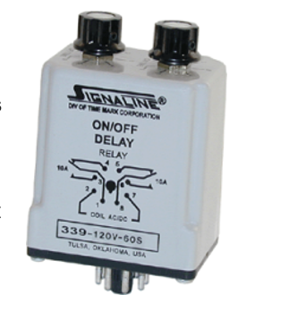
OFF-Delay Timers
This type of timer is sometimes called:
- Delay on break
- Release delay
- Delay on release
- Postpurge delay
- Delay on de-energization
The timer contacts open or close immediately after power is removed. The preset time delay must elapse before the contacts return to normal position and the load is de-energized.
Power must be applied before and during timing. Re-closing the control switch during the timing resets the time delay. Most reset on loss of power.
One Shot Timers
One shot timers are time delay relays and solid state timers that are also called:
- One shot relay
- Single shot
- Single shot interval
- Single pulse
- Latching relay
- Latching off delay
- Latching delay on de-energization
Contacts change position immediately upon application of power and remain in changed position for the preset time delay. After the time delay, the contacts return to their normal position. Power must be applied before and during timing. Reset occurs when the time delay is completed and the control switch is opened.
Interval Timers
Interval timers are time delay relays and solid state timers that are also called:
- On interval
- Pulse shaping
- Bypass timing
- Interval delay
- Delay on energization with instantaneous transfer
Time delay begins when power is applied. The output is energized during time delay and de-energizes at the end of the time delay, and it remains de-energized until power is removed.
Recycle Timers
Recycle timers are also called:
- Duty cycling
- Cycle
- Repeat cycle
- Delay on operate and on release
- ON/OFF dual delay
- Flasher
- Dual-delay energization
Timing function starts with closing of control switch. The load alternately turns on and off at regular intervals until power is removed. Removing power resets the time delay.
A time indicator records and displays elapsed time but performs no output function. Some timers can be programmed to function as a counter as well as timing functions. Time delay relays and solid-state timers are either single function or multi-function devices.
User Interface Specifications
Common user interface specifications for time delay relays and solid state timers include input controls and displays.
Input Controls
- None
- Analog
- Digital
Display Types
- None
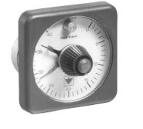
- Analog meters
- Simple visual indicators
- Digital numerical displays
Output specifications to consider when selecting time delay relays and solid state timers include the switch type, number of contacts, contact configuration, and pole and throw specifications.
Mountings and power supplies also need to be specified. Operating temperature is an important environmental parameter to consider when selecting time delay relays and solid state timers.
Standards
FAA AD 94-24-05 — Time delay relay\short Brothers PLC\sd3-60.
FORD EC2-1 — Nema solid state time delay relays.
MIL-C-83726/21 — Relays, time delay on operate, solid state (Type I).
Time Delay Relays FAQs
What is the difference between delay on and delay off timers?
Delay on timers activate their timing function after an input signal is received and a predetermined amount of time has passed.
Delay off timers start their timing function when the power supply is interrupted and release the output relay contacts after a predetermined amount of time.
What are the advantages of using time delay relays in industrial automation?
Time delay relays can control the sequence of operations in machinery, ensuring that each step occurs in the correct order and at the right time. This is crucial for complex processes where the timing of each operation affects the overall performance and safety of the system.
By delaying the start of equipment, time delay relays help prevent inrush current, which can cause electrical and mechanical stress on the system. This prolongs the lifespan of the equipment and reduces maintenance costs.
Time delay relays provide a delay before machinery starts or stops, ensuring that operators have enough time to move to a safe position. This is particularly important in environments where machinery poses a risk to human safety.
By controlling the timing of operations, time delay relays can help optimize energy usage. For example, they can ensure that equipment only runs when necessary, reducing energy consumption and operational costs.
Time delay relays come in various types, such as one shot timers, interval timers, delay on timers, and delay off timers, each suited for different applications. This versatility allows engineers to select the most appropriate relay for their specific needs.
With adjustable time settings and other user interface specifications, time delay relays offer precise control over process timing. This improves the accuracy and reliability of automated systems.
How do OFF-delay timers work?
When the power is initially supplied, the output relay contacts react immediately and move to their activated position.
The timing function of the OFF- delay timer begins when the power supply is interrupted. This means that the timer starts counting down the preset delay period as soon as the power is cut off.
During the timing period, the output relay contacts remain in their activated position. This ensures that the connected load continues to receive power or remain in its current state for the duration of the delay period.
Once the preset time period has elapsed, the output relay contacts release and return to their normal position. This effectively deactivates the connected load or changes its state as required.
This process ensures that the load remains powered or in its activated state for a specific period even after the power supply is interrupted, providing a controlled delay before deactivation.
How do one shot timers work?
When power is applied to the timer, the contacts change position immediately. This means that the relay activates and the connected load is either energized or de-energized depending on the configuration of the contacts.
The contacts remain in the changed position for a preset time delay. This timing period is determined by the settings on the timer and can be adjusted according to the specific application requirements.
After the preset time delay has elapsed, the contacts return to their normal position. This deactivates the relay and returns the connected load to its original state.
The timer typically resets when the time delay is completed and the control switch is opened. Additionally, power must be applied before and during the timing period for the timer to function correctly.
This process ensures that the load is controlled for a specific period immediately after power is applied, making one shot timers useful for applications requiring precise timing control.
How do ON-delay timers work?
When an input signal is received, the timing function of the on-delay timer begins. This means that the timer starts counting down the preset delay period as soon as the input signal is applied.
During the timing period, the contacts of the timer remain in their normal position. This ensures that the connected load does not change state immediately upon receiving the input signal.
Once the preset time delay has elapsed, the contacts of the timer change position. If the contacts are normally open (NO), they will close, energizing the load. If the contacts are normally closed (NC), they will open, de-energizing the load.
The timer typically resets when the input signal is removed. If the input signal is re-applied during the timing period, the timer resets and starts the timing function again from the beginning.
Delay-on timers open or close a switch’s contacts after an input signal is received and a predetermined amount of time has passed. This functionality is crucial for applications requiring a controlled delay before activating or deactivating a load.
Time Delay Relays Media Gallery
References
GlobalSpec—Electromechanical Timers
Image credits:
OMEGA Engineering, Inc. | Time Mark Corporation | Dynapar Sensors & Controls - Specialty Products
- Analog
- Analog Meter or Simple Visual Indicator
- Counter
- DIN Rail Mount
- Digital
- Digital Numerical Display
- Double Pole, Double Throw (DPDT)
- Double Pole, Single Throw (DPST)
- Electromechanical
- External
- Field Selectable
- Flange Mount
- Interval
- Multi Function
- Multiple Time Ranges
- Display: None
- Normally Closed (NC)
- Normally Open (NO)
- OFF-delay
- ON-delay
- One-shot
- PCB Mount
- Panel Mount
- Recycle
- Single Function
- Single Pole, Double Throw (SPDT)
- Single Pole, Single Throw (SPST)
- Single Time Range
- Socket / Plug-in
- Solid-state
- Time Indicator
- ABB solid state timer
- bistable display
- millisecond timer relay
- off delay timer relays
- one shot timer relays
- pneumatic time delay relays
- electro pneumatic time delay relay
- 12v delay timer relays
- 12VDC delay timer relays
- 24 hour timer relays
- 24 volt timer relays
- 3 phase time delay relays
- 480 volt time delay relays
- 6 volt time delay relays
- 9 volt timer relays
- AC delay timers
- dashpot timer relays
- electrical timer relays
- UJT SCR time delay circuits