Liquid Level Switches Information
 Liquid level switches detect liquid levels or interfaces between liquids such as oil and water, or liquid and solid interfaces. Liquid level switches are used in a number of liquid container monitoring applications including flow line monitoring, heaters and furnaces, as well as other household appliances, automotive applications, and control technology.
Switch Specifications
In order to select the proper liquid level switch, it is important to understand the various factors of a liquid level management system. The switch is a critical element in the system and when selecting a switch it is important to consider the type of measurement, the switch type, the configuration, and the pole and throw specifications.
Type of Measurement
Liquid level sensors provide measurement of the height or position of a fluid surface using a variety of different technologies and methods.
Optical sensors detect the decrease or change in transmission of infrared light emitted from a diode through a material.
Pressure membrane and differential sensors measure the pressure or change in pressure in a vessel such as a holding or storage tank.
Radar or microwave sensors measure using the emittance and detection of microwave pulses.
Ultrasonic or sonic liquid level sensors measure the length of time it takes for a reflected sound wave to return to a transducer from a target surface.
Vibrating or tuning fork liquid level sensors use a piezoelectric crystal or other technology to vibrate a probe and then monitor the presence, absence, increase or decrease of that vibration.
|
Technology |
Description |
Application |
|
Image Credit : Chipkin Automation Systems |
An air bubbler is composed of a source of compressed air, an air flow restrictor, sensing tube, and pressure transmitter. It works with a small amount of air metered into a dip tube in the tank. A pressure transducer monitors the air pressure in the tube to make sure the pressure in the tube equals the pressure at the bottom of the tank. The liquid's level is determined by dividing the pressure inside the tube by the liquid's density. The system is able to measure the liquid's level as directly proportional to the pressure as long as the material's density remains constant. Advantages: only the dip tube touches the media and needs to be compatible; point of contact does not have electrical parts; controls are located outside the tank making the system safer. |
An air bubbler system does not include any moving parts making them ideal for measuring the level of liquids, suspended solids, and sludge. Harsh environments, such as cooling towers, reservoirs, vented fuel tanks, drain sumps or air washers. |
|
Capacitive or radio frequency (RF) sensors
Image Credit: Sensors.mag |
The sensor is composed of a coaxial capacitor. All surfaces of the conductor are coated with a thin isolating layer to prevent an electric short circuit when it is immersed in the water tank. As the level of the tank increases water fills more space between the sensor’s coaxial conductors. This changes the average dielectric constant between the conductors and therefore changes the sensor’s capacitance. There is a level-capacitance dependence which provides a linear relationship. The slope depends on the liquid. Capacitance depends on temperature so a temperature sensor should always be present. |
Capacitive sensors are used in many industries including (but not limited to) chemical, food, water treatment, power, and breweries. |
|
Image Credit: Sensors.mag |
A differential pressure (DP) level sensor measures the difference in pressure between the top and bottom of a tank of fluid. The higher pressure, caused by the fluid, is compared to a lower reference pressure (generally atmospheric). Since the tank is open to the atmosphere, only the high pressure connection needs to be connected to the transmitter. The low pressure is released to the atmosphere so the pressure differential is the hydrostatic head (weight) of the liquid in the tank. The maximum height of liquid about the transmitter determines the maximum level measured. If the tank is not open to the atmosphere or is filled with a fluid other than water a different configuration is required. |
DP sensors are the most common sensor. |
|
Image Credit: Gems |
Conductive sensors are used for point-level sensing conductive liquids such as water and highly corrosive liquids. They use a low-voltage, current-limited power source applied across separate electrodes. Higher voltage sensors are designed to operate in less conductive (higher-resistance) media. These sensors are very safe due to the use of low voltages and currents. They are also simple to use and install but they must be checked for medium buildup on the probe so it continues to function properly. |
|
|
|
Mechanical, magnetic, or other float sensors involve the opening or closing of a mechanical switch. This occurs through direct contact with the switch or magnetic operation of a reed. Magnetic floats use a permanent magnet sealed inside a float which rises or falls to the actuation level. Mechanical floats use a miniature switch that the float moves against. Float level sensors cannot be used with highly vicious materials. Advantages: Low cost, simple, dependable. Image Credit: Babbitt Inc |
Float level sensors can be used to determine the interface level in oil-water separation systems, in multi-parameter sensor systems |
|
Image Credit: Gems |
Optical sensors use visible, infrared, or laser light to detect fluid level. They rely upon the light transmitting, reflecting, or refracting abilities of the material. Optical sensors can be used in contact and non-contact sensing. In non-contacting systems, the light aimed down on the surface of the fluid and the reflected light is detected by a photocell. Different fluids can be detected at different levels if multiple photocells are used. These sensors have a simple, straightforward design and are reliable sensors which do not be to be recalibrated between batches. They can be integrated in systems with a variety of process materials and process conditions. Their response time is virtually immediate and highly accurate. |
Optical sensors can be used to detect high foam levels or specific materials. They can also be used to determine if a material has reached a specific viscosity, density, opacity, or thermal conductivity condition. |
|
|
Pressure membrane meters have a pressure-sensitive switch. They transmit pressure to an internal sensor via an organic or thin-metal membrane. Pressure membranes measure level based on the principle that pressure is proportional to the level of liquid multiplied by the specific gravity. In these devices the level equals the hydrostatic head (pressure) measurement divided by the density of the liquid. Image Credit: National Instruments |
|
|
Image Credit: Babbitt Inc. |
Microwave (aka RADAR) sensors use electromagnetic energy instead of air molecules to transmit the energy so they will penetrate temperature and vapors layers and can be used in a vacuum. Electromagnetic energy is reflected by objects with high conductive properties like metal and conductive water. There are two basic processing techniques; Time-domain reflectromety (TDR) is a measurement of time of flight divided by the speed of light. FMCW techniques can be found in Doppler systems. Microwave sensors are executed at different frequencies. Generally, the higher the frequency, the more accurate and expensive the sensor. Non-contact technology. |
Microwave sensors are used in moist, vaporous, and dusty environments. They are also used in systems in which temperature varies. |
|
|
Radio frequency (RF) devices emit a high-frequency/low-power radio signal from a probe. When the material contacts the probe, the bridge becomes unbalanced and a comparing circuit realizes the change. This causes a relay output to change state. |
|
|
|
The sensors emit high-frequency acoustic waves that are reflected back to and detected by the emitting transducer. The sensor’s response is affected by turbulence, foam, steam, vapors, and changes in concentration. Proper mounting of the transducer is important to ensure a clear response to reflected sound and the tank should be free of objects that will distort the echo response. They can be used for continuous and point-level sensing as well as communicating with other devices. Ultrasonic level sensors are inexpensive and high functioning. Image Credit: Sensorsmag.com |
Ultrasonic level sensors are used for non-contact applications with highly viscous and bulk solids. They are used in systems which require remote, wireless monitoring and plant network communications. |
|
Tuning forks
Image Credit: Dwyer |
These sensors use various technologies (typically piezoelectric) to vibrate a probe at about 85Hz and then constantly monitor the changes in the vibrations. Tuning forks detect the dampening that occurs when a vibrating probe is submerged in a process media. The probe is vibrated by one piezoelectric crystal, while another piezoelectric crystal detects the vibration. There are three designs; reed, probe and tuning fork. The designs are distinguished by their configurations and operating frequencies. They can be used to detect for certain types of liquids. Tuning forks are simple, reliable, and can be cleaned in place. They can tolerate material build-up and can be coated for self-cleaning purposes. |


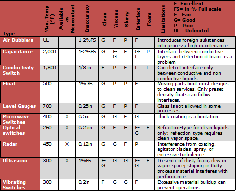
Table Credit: Omega Encyclopedia - Flow & Level Measurement
Switch Type
Electromechanical switch- Electromechanical switches have mechanical contacts or relays. These types of switches can control a wider range of current and voltage options. They are not affected by dirt, mist, magnetic fields or temperature ranges from near absolute zero to 1000°. Electromechanical switches can adapt to misalignment in installation/application to ensure there is no leakage current and making it available in many circuitry, actuator, and housing styles. Disadvantages include their price, limited contact life cycle, large size and slow response.
Solid-state switch - Solid-state switches are electric devices that do not have moving parts to wear out. They are able to switch faster without sparking between contacts or problems with contact corrosion. Their disadvantages include a high cost to build in very highcurrent ratings.
Configuration
When selecting a level switch, the user needs to determine if the electric circuit requires a normally open or normally closed switch.
- Normally open (NO) switches do not allow current to pass through in the free position. They need to "make" a contact to be activated.
-
Normally closed (NC) switches allow current to pass through in the free position and need to "break" contact (open) to be activated.
Pole/Throw
Most switches have one or two poles and one or two throws, but some manufacturers will produce custom level switches for special applications. The number of poles describes the number of separate circuits which can pass through the switch at the same time. The number of throws describes the number of circuits each pole can control. This is noted by the configuration of the circuit (NO/NC). Breaks are interruptions to the circuit caused by the separated contacts the switch introduces into each circuits it opens or interrupts in the circuit.
Single Pole, Single Throw (SPST) - Single pole, single throw (SPST) switches make or break the connection of a single conductor in a single branch circuit. They usually have two terminals and are referred to as single-pole switches
Single Pole, Double Throw (SPDT) - Single pole, double throw (SPDT) switches make or break the connection of a single conductor with either one of the two other single conductors. They usually have three terminals and are commonly used in pairs. SPDT switches are sometimes called three-way switches.
Double Pole, Single Throw (DPST) - Double pole, single throw (DPST) switches make or break the connection of two circuit conductors in a single-branch circuit. They typically have six terminals and are available in both momentary and maintained contact versions.
Double Pole, Double Throw (DPDT) - Double pole, double throw (DPDT) switches make or break the connection of two conductors to two separate circuits. They typically have six terminals and are available in both momentary and maintained contact versions.
Other- Other, special throw types with more than two poles. Examples include switches that are designed to split loads into separate circuits (e.g., headlamp switch).
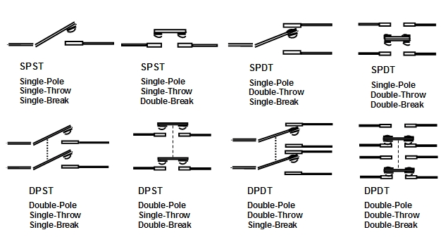
Image Credit: Digi-Key
Measuring Range
The measuring range is probably the most important specification to examine when choosing liquid level switches. It is defined as the level range that devices can measure. Measuring range is determined by the maximum and minimum media levels. The user should also account for anticipated media level fluctuations. If the proper measuring range is selected, less data will be lost during an event which exceeds the measuring range.
- Allowable sensor over-range- Overrange specification limits the range of matching products to the specified range multiplied by a selected overrange factor. This keeps returned matches close to the range requirement and filters out products with a wider range than needed. "From," "To," and "Overrange" must all be specified to activate this option.
Example: User specifies a sensor with a range from 0-100. Without overrange specification, sensors with ranges of 0-100, 0-1000, and -10,000 to +10,000 are returned as matches. An overrange specification of 50% will filter out any sensors with a full scale range greater than 150.
Electrical Specifications
Also of critical concern are the ratings for current and voltage the switches require. Analog outputs from level switches can be current or voltage signals. Also possible is a pulse or frequency.
- Maximum current- The device's maximum nominal (name plate) current-carrying capacity.
- Maximum AC voltage- The device's maximum AC voltage rating.
- Maximum DC voltage- The device's maximum DC voltage rating.
- Transistor- transistor logic (TTL) - TTL driver circuitry enables the status of the switch to be controlled by the level of the TTL logic input. Power can be applied across a pair of designated power terminals and then control the switch operation with a 5 volt control circuit.
Communication Interface
There are two basic communication interfaces:
Serial - Serial communication means that data bits are sent in a serial (one after another) way over a single line. The advantages of serial communication are that the data can be sent further, and the cable connection is simpler and uses fewer wires. Serial interfaces use a serial communication protocol such as universal serial bus (USB), RS232, or RS485.
Parallel - Parallel communication means that a number of data bits are sent at the same time. More information can be sent quickly and more reliably, but the processing time is longer. Parallel interfaces use a parallel communication protocol such as general-purpose interface bus (GPIB).
Process Specifications
- Process operating conditions - There are two process operating conditions to consider:
- Maximum operating pressure - The maximum operating pressure of the material for which the device is rated.
- Material temperature range - The maximum material temperature for which the device is rated.
- Liquid specific gravity - The liquid specific gravity is the relative density of a substance to the density of water at 4°C.
The density can be calculated using the following equation:
Specific Gravity = Density of liquid (g/mL)/ Density of water (1.00 g/mL),
with density of water defined as weight/volume
The specific gravity of some common liquids can be found here.
Mounting Styles
Mounting styles are defined as side-mount, top-mount, and bottom-mount. Mounting the sensor depends on pre-exiting system conditions, container characteristics, and if the sensor is for contact or non-contact measurements. These switches can be mounted on the top, bottom, or side of the container holding the substance to be measured. Some factors to consider when selecting a mounting option are the package size of switch or sensor, and the space available in the application. The switch should be rugged to handle the environment of the system.
Features
Some features that can make liquid level switches more desirable are being programmable, having controller, recorder, or totalizer functions, and a built-in alarm indicator, whether audible or visible.
- Devices with field adjustable measurement ranges allow for the user to adjust the measuring range depending on the media container and the environment conditions.
- Rated for Sanitary Applications- Devices are rated for sanitary applications such as those found in the pharmaceutical and food processing industries.
- Handles Slurries /Suspended Solids-Devices can handle slurries or suspended solids such as sewage and waste water.
- Built-in Alarm / Indicator- Devices have a built-in audible or visual alarm that is more than a switch or relay closure.
- Programmable- Devices can be programmed for different ranges, materials, output, etc.
- Controller Functions- Devices have or take sensor inputs, provide control functions (e.g., limits, PID, logic), and output a control signal.
Applications
Liquid level monitoring is important in a wide variety of applications. Any industrial process involving the filling or storing of a liquid in a tank or vessel would benefit from the use of a liquid level switch. They are also an important part of process control systems which manages flow rate into and out of a storage vat or reactor.
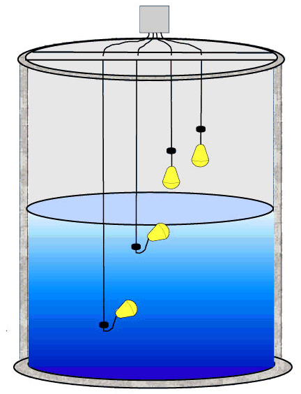
Image Credit: cmcontrols.com
Liquid level switches can be used for high or low level sensing and alarms, leak detection, overfill shutoff, and regulating the interface between levels of different media. They are found in a wide variety of industries-- not limited to-- manufacturing, food and beverage, chemical and pharmaceutical, marine, medical, and fuel/energy management.
Video credit: uncleculdesac / CC BY 3.0
Resources
Introduction to Level Measurement
What's the Right Level Technology for Your Application?
Fraden, Jacob. Handbook of Modern Sensors: Physics, Designs, and Applications. New York: Springer, 2010. Print.
A Level Measurement Orientation
Newark - Selecting the correct floatswitch (pdf)
Omega Encyclopedia - Flow & Level Measurement
Image credit:
- Air Bubbler
- Bottom mount
- Built in alarm indicator
- Can handle liquids with suspended solids (slurries)
- Capacitive / RF Admittance
- Controller Functions
- Double Pole, Double Throw (DPDT)
- Electrical Conductivity or Resistance
- Electromechanical Switch
- Field Adjustable Measurement Ranges
- Mechanical / Magnetic Floats
- Normally Closed (NC)
- Normally Open (NO)
- Optical
- Programmable
- Radio Frequency
- Rotation Paddle
- Sanitary Applications rated (3A etc.)
- Serial Interface
- Side mount
- Single Pole, Double Throw (SPDT)
- Single Pole, Single Throw (SPST)
- Solid-State Switch
- Top mount
- Ultrasonic / Sonic
- Vibrating / Tuning Fork Method