The power stage of an isolated buck converter in its simplest form is presented in Figure 1.1. Depending on the output loading and the value of filter inductor L, the power stage can be operated in two distinctive modes: continuous conduction mode (CCM) and discontinuous conduction mode (DCM). In the CCM, the inductor current, i, always stays above zero. In the DCM, the current, for a certain duration, stays at zero. It is also understood that, in the CCM, the power stage alternates between two topologies while, on the contrary, it experiences three in the DCM.
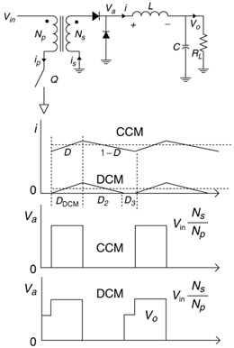 Figure 1.1: Power stage of an ideal forward converter
 1.1 CCM Open-Loop Output and Duty Cycle Determination
If ideal rectifiers are assumed and series losses are ignored, the requirement of flux conservation, that is, the volt-second balance, across the inductor gives
| (1.1) | 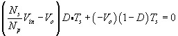
|
when the circuit alternates between two topologies under the steady state with a defined switch( Q)-on duty cycle, D, and a given clock rate T s. Obviously, (1.1) results in
| (1.2) | 
|
As a matter of fact, (1.2) can also be given a different interpretation. That is, the rectangular wave, V a, driving the loaded LC filter contains a DC component:
| (1.3) | 
|
This latter view aligns well with the ultimate goal of the converter operation, extracting the average voltage embedded in the transformed input drive and regulating the output voltage by fine-tuning the turn ratio with variable duty cycle, D.
However, in reaching (1.1) (1.3), we made...
Copyright Elsevier Inc. 2006 under license agreement with Books24x7