Switch-Mode Power Converters: Design and Analysis

1.2: DCM Open-Loop Output and Duty Cycle Determination

1.2 DCM Open-Loop Output and Duty Cycle Determination

The DCM operation is rarely used for actual design. However, it does have educational merits from an analytical point of view. We consider only diode losses for demonstration purposes. As shown in Figure 1.1, there are three distinctive operation intervals for the DCM. It is no longer a simple task identifying the duty cycle using the concept of volt-second balance alone. Yes, the concept is still, and always, applicable, but we need more than that. Again, we first apply Faraday's law of flux conservation:

(1.12)

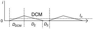
Equation (1.12), however, has two unknowns, D DCM and D 2. We need one more equation. This need can be met by examining the inductor current form given in Figure 1.3.


Figure 1.3: Inductor current for DCM

The key is the fact that the load current, I o, equals the average value contained in the current waveform. That is,

(1.13)

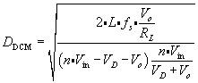
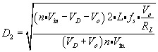
Equations (1.12) and (1.13) can then be solved together and the symbolic solutions are

(1.14)
(1.15)

UNLIMITED FREE
ACCESS
TO THE WORLD'S BEST IDEAS

SUBMIT
Already a GlobalSpec user? Log in.

This is embarrasing...

An error occurred while processing the form. Please try again in a few minutes.

Customize Your GlobalSpec Experience

Category: Loop Powered Devices
Finish!
Privacy Policy

This is embarrasing...

An error occurred while processing the form. Please try again in a few minutes.