The average current-mode control, in contrast to the peak current-mode, was claimed by Tang and Lee [3] to offer several advantages. However, in treating the topic, many existing studies did not handle the analytical procedure properly. This chapter gives an in-depth analysis of the subject. All discussions refer to Figure 3.1, which depicts a complete, nonisolated forward converter using average current-mode control.
3.1 Average Current Feedback
Under CCM operation, the output filter inductor, L, current is known to exhibit a waveform as shown in Figure 3.2.
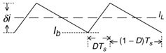 Figure 3.2: Inductor current profile
 The steady-state current feedback signal, including the sense resistor, R i, can be described as
| (3.1) | 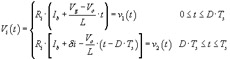
|
where
and V g is the line input voltage; ? i, the peak-to-peak ripple current; D, the steady-state duty cycle; T s, the switching period; V o the regulated output. Then, at the inverting input node, V a, and the node V b, two differential equations can be written:
| (3.2) | 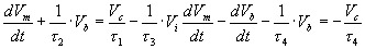
|
where
The equations in (3.2) are consolidated into a single one for node voltage V b:
| (3.3) | 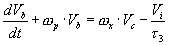
|
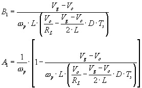
where
Equation (3.3), together with the cyclic input functions of (3.1), can be solved for the two time segments in the steady state with the assumption of two unknown, cyclic starting states, V bx and V by, at the beginning of each segment. The solutions for node voltage V b are
| (3.4) | 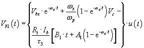
|
where
and