1.4 Gain Formula for Nonideal Operational Amplifiers
In most existing electronics textbooks dealing with operational amplifiers, the concept of virtual ground, Figure 1.5, is often invoked. The concept emerges from the assumption that both the noninverting, V 1, and inverting, V 2, inputs track each other and that one of the inputs is generally at a fixed DC voltage. As a result, both inputs can be treated as zero potential for signal analysis purposes. However, both the logic and the concept suffer unnecessarily from many deficiencies. The first, and perhaps the worst of all, is the assumption of infinite gain and bandwidth. Second, and no worse, is the missing information about the DC operating state. Third, the nonideal open-loop gain is not accounted for.
 Figure 1.5: (a) Typical op-amp circuit, (b) inverting configuration
 The situation can be improved significantly by getting rid of the virtual ground concept and using the voltage view and the superposition principle. Referring to Figure 1.6, the noninverting node gives V p = V ref, while the inverting node gives
| (1.20) | 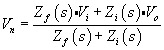
|
The output is therefore given as
| (1.21) | 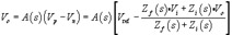
|
With further manipulation, (1.21) gives
| (1.22) | 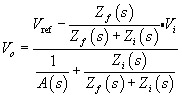
|
If A( s) ? 0, (1.22) degenerates into
| (1.23) | 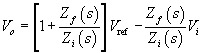
|
 Figure 1.6: General op-amp circuit
 This is the form given in many books with the assumption of infinite open-loop gain and bandwidth. However, we stick with (1.22) from here on, since it accounts for the nonideal gain A( s). As a matter of fact,...