1.11 CCM Current-Mode Control Small-Signal Stability
In the previous section, it was mentioned that the sole difference between Figures 1.10 and 1.23 is the PWM block. This statement holds true for AC small-signal studies. We then modify whatever surrounds the PWM, F m, in Figure 1.16. This is done by expressing the total derivative of (1.52) in terms of three partial derivatives against error voltage perturbation, input disturbance, and output deviation:
| (1.55) | 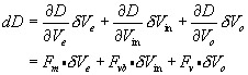
|
where, for instance,
| (1.56) | 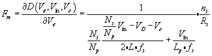
|
The other two gain coefficients, F vb( = ?D/ ?V in) and F v( = ?D/ ?V o), in symbolic forms are extremely burdensome to write and omitted in print with the understanding that they are readily computable given modern software. Anyway, (1.55) needs a new block description, Figure 1.24, for a current-mode PWM.
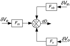 Figure 1.24: A current-mode CCM PWM
 Then, using Figure 1.24, we replace the F m block in Figure 1.16. The complete block diagram, Figure 1.25, for CCM operation is done. It clearly reflects the added complexity of the current-mode control mechanism.
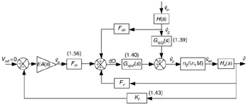 Figure 1.25: Closed-loop AC block diagram for the CCM current mode
 Again, for loop gain evaluation, Figure 1.25 is simplified by assuming constant input. This simplification leads to Figure 1.26.
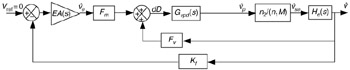 Figure 1.26: CCM current-mode closed-loop diagram for loop gain
 Figure 1.26 shows two loops, an inner current loop and an outer voltage loop. We first absorb the current loop, and Figure 1.26 is further simplified to Figure...