1.10 CCM Current-Mode Control in a Closed-Loop Steady State
In the previous section, the general feature of current-mode operation and its advantages were briefly reviewed. In this section, we give a thorough treatment of CCM. For that, we refer to Figure 1.1 (or 1.2). The primary winding current (switch current) is understood to consist of three components: the reflected load, the reflected ripple of the output inductor, and the primary magnetization, L p. Given in Figure 1.22, these will help us formulate and perform the analysis to follow.
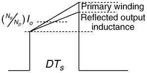 Figure 1.22: Main switch current composition
 The total ramp-up current profile can be written as
| (1.50) | 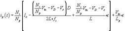
|
Referring also to Figure 1.19 and assuming a 1-to- n i, current transformer, the steady-state open-loop duty cycle is therefore decided when the ramp-up signal meets the error voltage; that is,
| (1.51) | 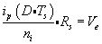
|
or
| (1.52) | 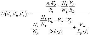
|
Compared with (1.28) for voltage-mode control, the intricacy of current-mode control is simply amazing. It seems to have built-in intelligence by incorporating all the essential variables. Moreover, we can easily modify Figure 1.10 and infuse it with the sophistication of current-mode control. This leads to Figure 1.23, in which only the mechanism of the PWM is modified.
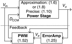 Figure 1.23: Current-mode buck converter in a CCM closed loop
 For those of you interested in the closed-loop output, we do the following procedure. But, considering that (1.10) is too prohibitively complicated to use, we invoke only (1.6), the approximation. Starting from (1.6), we replace the variable D with (1.52):
| (1.53) | 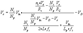
|
We...