1.5 Feedback Under Voltage-Mode Control
To obtain a precise and well-regulated output voltage against input or load changes, a feedback technique is always used in modern switch-mode power converters. Early converters, in the 1960s, tended to use voltage-mode control alone. By the late 1970s, the concept of current-mode control began to show up. A typical voltage-mode control scheme is shown in Figure 1.7.
 Figure 1.7: Voltage-mode control scheme
 In this scheme, the output to be regulated is fed back through a resistive voltage divider and compared with a precision reference voltage, V ref. The error voltage, V e, is then feeding a pulsewidth modulator, which has an embedded sawtooth reference. We develop the feedback path gains based on this typical schematic. First, the error amplifier and its associated circuit is depicted in its steady-state form (Figure 1.8).
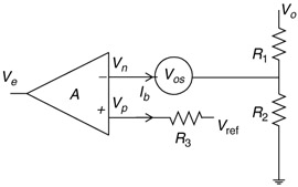 Figure 1.8: Error amplifier
 It is fairly straightforward to show that the error voltage is
| (1.25) | 
|
where op-amp offset voltage and bias current are also accounted for.
Next the PWM gain is derived. In the case of voltage-mode control, it is again quite simple. The circuit surrounding the PWM is given a little more detail as shown in Figure 1.9.
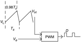 Figure 1.9: PWM block and external sawtooth
 The sawtooth reference is a periodic clock consisting of two parts, the active up ramp and the dead-time down ramp. In general, the up ramp takes up 98% of the clock cycle and the down ramp the remaining 2%. The reference swings between two...