The equivalent circuit for the current sensor with additional filter ( R f and C f) is depicted in Figure 1.30. For the steady-state analysis, the driving current source is placed in ( a + bt) form by rewriting equation (1.50). It is understood that
| (A.1) | 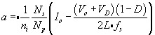
|
| (A.2) | 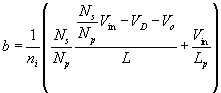
|
Given an unknown initial voltage, V ?, the output voltage in Laplace transformation form is
| (A.3) | 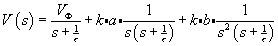
|
where
During the on-time D T s, the output voltage in time domain is given as
| (A.4) | 
|
while during the off-time it is given as
| (A.5) | 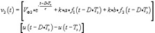
|
where f 1( t) and f 2( t) are the inverse transforms of their corresponding transfer functions in (A.3).
The continuity of states at the time-domain transition boundaries requires
| (A.6) | 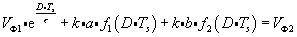
|
| (A.7) | 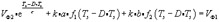
|
Both unknowns, V ?1 and V ?2, can be solved from (A.6) and (A.7) and expressed in terms of V in, V o, D, and other components. The steady-state duty cycle is then determined by
| (A.8) | 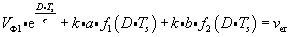
|
We define an implicit function
| (A.9) | 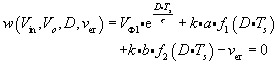
|
Copyright Elsevier Inc. 2006 under license agreement with Books24x7