1.3 CCM to DCM Transition, Critical Inductance
It is very interesting to compare (1.5) and (1.14). The obvious difference is in the form of equation (1.5), which is very simple, while (1.14) looks formidable with all circuit components and switching frequency, f s, involved in setting the duty cycle. Readers may then ask, What critical part does a designer control to determine the mode of operation? The answer is the inductor. Given the required input, output, loading, and selected switching frequency, there is a critical inductor value that marks the boundary of CCM to DCM transition. How do we obtain that value? There is more than one way to determine the critical value. We will present two approaches.
The first approach recognizes that, when the operating condition changes to a point, the DCM duty cycle equals that of the CCM:
| (1.16) | 
|
Equation (1.16) yields the critical inductance:
| (1.17) | 
|
The other approach takes a little extra effort but gives additional insight. This time, the inductor current under the CCM operation is reexamined in Figure 1.4. An AC ripple current is superimposed on top of the DC load current, I o.
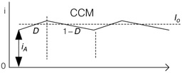 Figure 1.4: Inductor current for CCM
 The ripple current has a magnitude of
| (1.18) | 
|
The trough magnitude is therefore
| (1.19) | 
|
It is easy to see that the power stage enters the DCM operation when the trough current equals zero. In other words, the condition i A = 0 gives the critical inductance, and it is the same as...


 TABLE OF CONTENTS