This volume is part of the Practical Guide Series developed and published by the ISA, the International Society for Measurement and Control. The Practical Guides were conceived because of a shortage of published material in the field of measurement and control that bridges the gap between theory and actual industrial practice. Many books in the field have catered to the needs of technical students, who need to be oriented to basic control theory and concepts, or college-level readers, who are interested in engineering mainly from a classroom perspective. There are handbooks for practicing engineers that cover measurement and control, but these handbooks often devote only a chapter or two to topics that merit more attention. Within the Practical Guides Series, separate volumes address each of the important topics and give them comprehensive, book-length treatments. Each book in the series can be understood and used by technical students, sales engineers, sales personnel, and managers, and relied upon by those who have "real-live" industrial concerns such as correct application, safety, installation, and maintenance. Another unique feature of the Practical Guides is the stress placed on the actual experience of measurement and control practitioners. The Practical Guides are overseen by various Volume Editors and a Series Technical Editor, who have extensive experience in measurement and control. The Volume Editors have been selected for their specific expertise in the volume topics, and bring together numerous Contributing Writers with even more specialized knowledge. The Series Technical Editor, who is responsible for general technical consistency within each volume and across all volumes, helps guide the Volume Editors. The Practical Guides capture the hard-earned experience of the writers and, by employing examples and recording anecdotal observations, make that experience as applicable for the reader as possible. Case studies, either hypothetical or based on real case histories, are used to illustrate typical situations and show how good planning and practical applications made the difference between success and failure. Some of this information has never been documented before. This volume is designed to be at home in a library, in a classroom, or on the plant floor. The comfortable reading style, large pages, and frequent illustrations will contribute to ease of use. The page design uses graphics to "call out" some of the major points of the text, such as crucial safety checks and important examples. Each Practical Guide gathers widely scattered information in a single text, with bibliographies directing the reader to other sources. |
Chapter 10.6 - Control Valve Features: Bonnets
Bonnets A valve bonnet covers the opening through which the internal parts are inserted. The bonnet serves as the mounting base for the actuator. It includes the seal which prevents fluid leakage along the stem. The bonnet also contains the packing box. The importance of properly mounting the actuator on the valve body cannot be over-emphasized. Improperly mounted hardware is dangerous - in addition to potential operator injury in the event they become loose, improper mountings may have the following detrimental effects:
Special valve bonnet assemblies are available to address difficult service conditions. Most common are extension and bellows seal bonnets. Extension bonnets can be used in either high or low temperature applications. They can protect packing from temperature extremes, allow clearance for pipe insulation and isolate actuators from hot pipelines. Packing hold down bolts can also have live loading Belleville washers to keep proper, continuous tension on the packing. Extension bonnets are available in either cast or fabricated construction. Many high pressure valves installed for elevated temperature service include bonnet extensions as a secondary design feature. Bellows seal bonnets are used where no leakage along the stem can be tolerated, as in toxic, volatile or radioactive process fluid operations. This construction prevents both the stem and packing from contact with the process fluid. Due to construction constraints and cost, selection of a bellows seal design should be carefully considered. Particular attention should be addressed to the details of inspection and maintenance procedures after installation. Bonnet Joining Methods The methods of joining the bonnet to the valve body are:
The bonnet to valve joining methods above are listed in order of increasing severity of service. The bonnet is a pressure carrying part, sealing the contained fluid from the outside. THREADED BONNETS These are used on low-pressure valves handling non-corrosive, non-hazardous fluids, in valve sizes below 2 inches. These are rare for control valves. Threaded bonnets reduce total weight and are economically constructed. Their major disadvantage is the difficulty in removal after extended service. 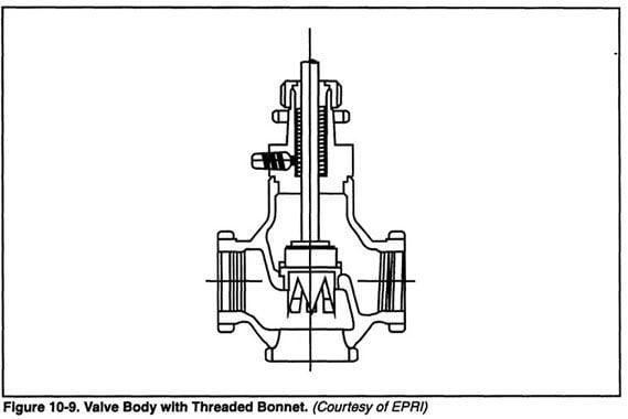 UNION BONNETS These are an improvement over the threaded type for valves under 2 inches used in ordinary applications. The union's closure surfaces do not scrape past eacl other. Instead, the union threads draw the surfaces tightly into contact. This construction has the advantage of preventing any motion between the joint faces as the joint is being tightened. 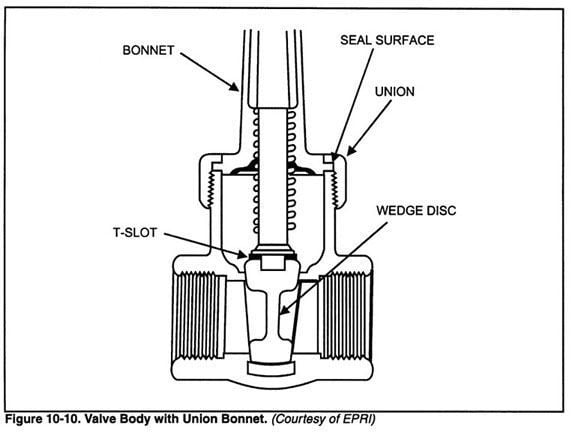 FLANGED BONNETS This is the most common type of bonnet connection. Flanged bonnets can be used for large sized valves operating in moderate pressures and temperatures. The bonnet and bottom flange are usually stud bolted. These may consist of studs threaded into the bonnet neck of the body or through the bonnet flange. 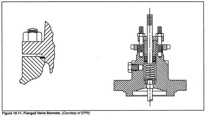 PRESSURE SEALED BONNETS The pressure sealed bonnet is used on some high pressure (over 900 psi) and high temperature (over 500° F) service valves. It consists of a pressure activated metal seal ring and a bridge lock thread engagement. Figure 10-12 portrays a pressure sealed bonnet assembly. The most important advantage of this design is the absence of a large bonnet flange which can be subjected to high internal stresses caused by frequent thermal shocks or thermal cycling. 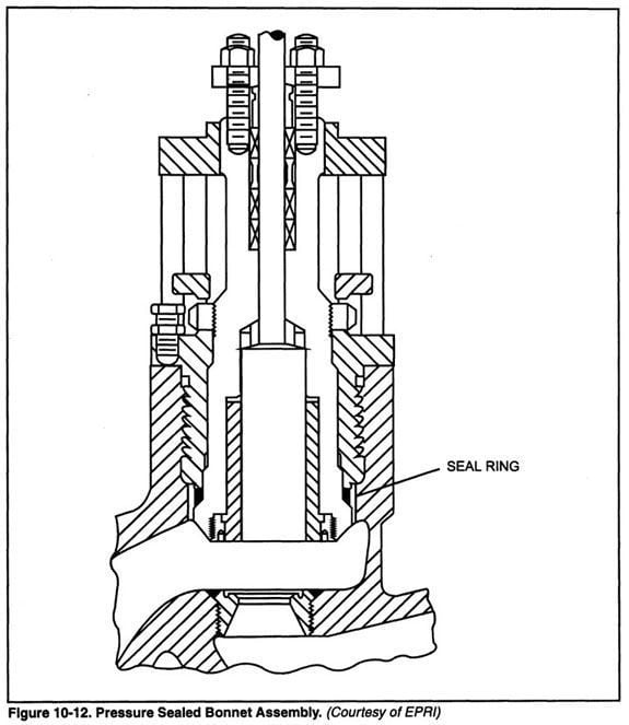 The plug guide bushing is constructed of a hard material such as heat-treated ANSI / ASTM type 440-C stainless or 17-4-PH stainless steel. For corrosive or cryogenic applications special guide materials, such as glass filled Teflon, are available. The guide bushings are either pressed in or permanently held by a retainer. The upper portion of the bonnet contains the valve packing or the stem seal. The pressure sealed bonnet overcomes the weight disadvantage of flanged bonnets on large valves by allowing the fluid pressure to tighten the joint. The bonnet seal becomes tighter as the fluid pressure increases. EXTENSION AND FINNED BONNETS Extension bonnets place the packing far enough away from the cold area of the valve to prevent freeze-up of the packing in cryogenic applications. A tubular connection separates the cryogenic area from the flange. An extension bonnet can be used not only for temperatures below 32F, but also for elevated temperatures above 450F. 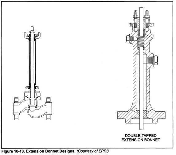
|
For the elevated temperature services it has been customary to cast either horizontal or vertical cooling fins onto the bonnet extension to provide sufficient radiating heat loss. Figure 10-14 shows such a "radiating" fin bonnet. Recent designs have been able to eliminate the fins. A plain, well designed extension bonnet will provide sufficient radiating surface, in combination with a limited cross-section for heat conduction, to maintain the packing within acceptable temperature limits. 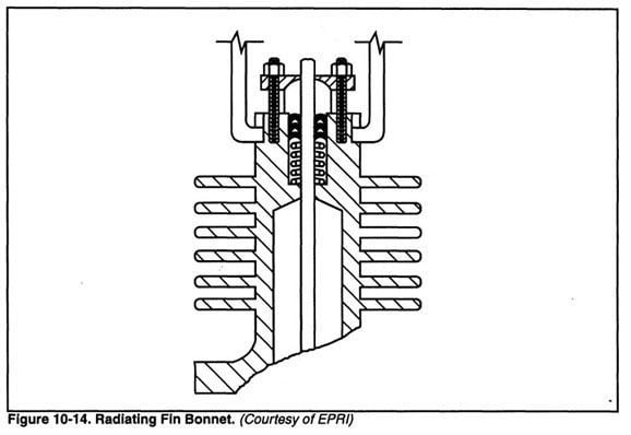 | An extended bonnet with fin sections should never be covered with thermal insulation. In general, the use of a bonnet of this type will radiate internal heat. |
BELLOWS SEAL BONNETS This assembly uses a bellows for sealing against leakage around the valve stem. For valves handling toxic fluids or for radioactive services where leakage cannot be tolerated, the bellows seal bonnet should be specified. A bellows seal can consist of either a hydro-formed metal bellows or a welded leaf-type bellows. This surrounds the valve stem and forms a completely enclosed metal seal for the moving valve stem. Bellows seals are either internally or externally pressurized. In the internally pressurized version shown in Figure 10-15, only the inner surface of the bellows is subjected to the fluid pressure. This saves cost for corrosive fluid service because the outer-extension bonnet can be made of carbon steel. The externally pressurized bellows can operate at higher pressure ratings. A well designed bellows seal has an anti-rotation device which prevents bellows damage during assembly and disassembly. One disadvantage of the bellows seal is its relatively low pressure rating. The pressure ratings decrease with increasing valve size. Typical ratings are 500 psi at 500F decreasing to 150 psi at 600F. Higher ratings can be achieved by the use of special bellows with increased wall thickness. Unfortunately, this is done at the expense of reducing the number of obtainable life cycles. Shorter strokes can also give higher pressure ratings. 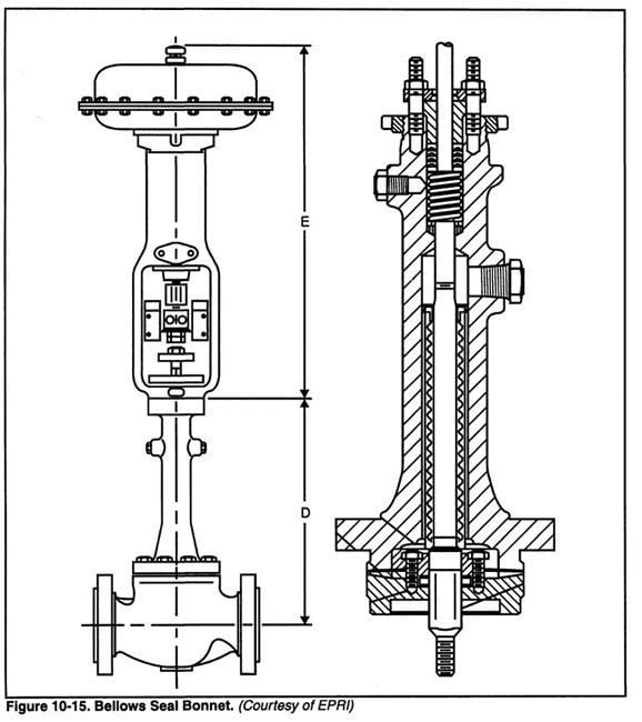 Bonnet Stud Fatigue Bonnet stud fatigue may occur in valves controlling the discharge of high pressure duplex reciprocating pumps. Pulsation fatigue tests have shown that an adequately stiff bonnet design and alloy steel bolting stressed to 45,000 psi give satisfactory performance. Torque wrenches should be used when re-assembling the joint after field maintenance to ensure uniform loading of all studs. |