This volume is part of the Practical Guide Series developed and published by the ISA, the International Society for Measurement and Control. The Practical Guides were conceived because of a shortage of published material in the field of measurement and control that bridges the gap between theory and actual industrial practice. Many books in the field have catered to the needs of technical students, who need to be oriented to basic control theory and concepts, or college-level readers, who are interested in engineering mainly from a classroom perspective. There are handbooks for practicing engineers that cover measurement and control, but these handbooks often devote only a chapter or two to topics that merit more attention. Within the Practical Guides Series, separate volumes address each of the important topics and give them comprehensive, book-length treatments. Each book in the series can be understood and used by technical students, sales engineers, sales personnel, and managers, and relied upon by those who have "real-live" industrial concerns such as correct application, safety, installation, and maintenance. Another unique feature of the Practical Guides is the stress placed on the actual experience of measurement and control practitioners. The Practical Guides are overseen by various Volume Editors and a Series Technical Editor, who have extensive experience in measurement and control. The Volume Editors have been selected for their specific expertise in the volume topics, and bring together numerous Contributing Writers with even more specialized knowledge. The Series Technical Editor, who is responsible for general technical consistency within each volume and across all volumes, helps guide the Volume Editors. The Practical Guides capture the hard-earned experience of the writers and, by employing examples and recording anecdotal observations, make that experience as applicable for the reader as possible. Case studies, either hypothetical or based on real case histories, are used to illustrate typical situations and show how good planning and practical applications made the difference between success and failure. Some of this information has never been documented before. This volume is designed to be at home in a library, in a classroom, or on the plant floor. The comfortable reading style, large pages, and frequent illustrations will contribute to ease of use. The page design uses graphics to "call out" some of the major points of the text, such as crucial safety checks and important examples. Each Practical Guide gathers widely scattered information in a single text, with bibliographies directing the reader to other sources. |
Chapter 10.19 - Control Valve Features: Traps, Strainers and Filters
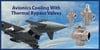
Traps, Strainers and Filters In any industrial plant, two-phase flows are common. Condensate in steam, air and water-vapor bubbles in water or dirt and residues in other process streams. It is sometimes necessary to remove a phase to improve heat transfer or to prevent damage to piping components or equipment. In many cases, large scale equipment may be required, such as knockout drums, separators or filtration units. These are not within the scope of this presentation. However, smaller components, such as traps and strainers or filters, can be considered parts or auxiliary components to enable proper valve operation. Upstream Strainers for Valves and Regulators The function of the strainer is to protect the valve or regulator from entraining dirt, scale or other solid substances carried in the process liquid, gas or vapor. Strainers are installed upstream from the valve or regulator to be protected at a minimum distance of 3'-0" of straight pipe. In hot vapor installations, upstream and downstream piping in the vicinity of the valve or regulator must be insulated to minimize condensation. Strainers are available in 1/4" through 2" cast iron construction for up to 400 psig at 100F. End connections can be threaded (Figure 10-35) or flanged. Various screen perforation sizes are available, and are determined by the line size and screen diameter. Strainers are installed with a drain valve at the screen outlet to facilitate frequent flushing. Strainers and drain valves must be provided, each with isolation valves to enable safe removal and/or cleaning. Chapter 18 includes an example of a problem caused by a plugged strainer. 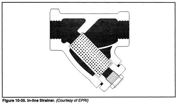 A strainer consists of a perforated surface through which all the fluid flow passes, leaving solids above a maximum size, dependent on the size and shape of the perforations in the surface. The surface can be a woven screen, which is common for the small strainers that protect instruments, traps and steam or water valves. The simplest of strainers are flat plates inserted at mating flanges. The plate must be strong enough to resist rupture from pressure differential if the holes become totally clogged with solid debris. The capacity of a flat plate strainer is so limited that a cone form is preferred. Either form can be a temporary strainer for startup and cleanout of lines after installation or repairs. A cylindrical form of strainer element has much more debris retaining capacity, and is more resistant to high pressure differentials. The strainer element, called a basket in larger versions, is removable for cleaning. Flow path through the strainer body in small units is angled down into the element interior, then outward into the body at 45° to the line and on into the line again. This allows the element to be closed off at the bottom by a pipe plug, removable to allow cleaning, or by a connection with the valve to allow blowout of the debris from the element interior. Information required when ordering strainers is typically:
Steam Traps Steam traps are installed in steam lines to allow discharge of condensate and air while preventing loss of steam. The purpose of the steam trap is the discharge of condensate and non-condensable gases while preventing escape of live steam. The trap must be able to sense the difference and act accordingly. In the power plant, most traps remove condensate from steam lines. The condensate may be in large intermittent quantities, such as occur on start-up of a cold line or the quantities may be consistently large as for a constant heating or process load. A low, steady load can exist in a drain for a large insulated line that is shut off or carrying a light load. A trap must also discharge air and other non-condensable gases from the steam piping. This is a factor in trap design and selection. UPSTREAM STRAINERS FOR STEAM TRAPS Good trap installations have strainers mounted in the steam line ahead of the trap. Poor trap performance may be caused by a strainer that has accumulated too much dirt, scale or pipe or corrosion treatment components carried from a boiler. If the strainer has a clean out valve on it, this can be used to slowly open the valve and blow out the deposit. If this does not unclog the strainer, it should be disassembled and the strainer soaked in penetrating oil. Severe blockage of the strainer may necessitate its replacement. Filters Removal of water or oil from gas or vapor can be done by filters. Some of these are small and easy to install in a piping run. The liquid usually drains into a small tank and leaves the piping through a trap (the device that prevents gas or vapor escape but releases the liquid). Filters such as the one shown in Figure 10-36 are used with pilot operated gas pressure regulators, but can also be used for filtering air supply pressure to instruments mounted on valves. 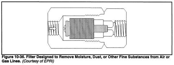  The filter shown in Figure 10-37 is used to protect a variety of equipment such as control valve actuators, controllers and the like. Connections are usually 1/2", 3/4" or 1" NPT inlet and outlet. |