This volume is part of the Practical Guide Series developed and published by the ISA, the International Society for Measurement and Control. The Practical Guides were conceived because of a shortage of published material in the field of measurement and control that bridges the gap between theory and actual industrial practice. Many books in the field have catered to the needs of technical students, who need to be oriented to basic control theory and concepts, or college-level readers, who are interested in engineering mainly from a classroom perspective. There are handbooks for practicing engineers that cover measurement and control, but these handbooks often devote only a chapter or two to topics that merit more attention. Within the Practical Guides Series, separate volumes address each of the important topics and give them comprehensive, book-length treatments. Each book in the series can be understood and used by technical students, sales engineers, sales personnel, and managers, and relied upon by those who have "real-live" industrial concerns such as correct application, safety, installation, and maintenance. Another unique feature of the Practical Guides is the stress placed on the actual experience of measurement and control practitioners. The Practical Guides are overseen by various Volume Editors and a Series Technical Editor, who have extensive experience in measurement and control. The Volume Editors have been selected for their specific expertise in the volume topics, and bring together numerous Contributing Writers with even more specialized knowledge. The Series Technical Editor, who is responsible for general technical consistency within each volume and across all volumes, helps guide the Volume Editors. The Practical Guides capture the hard-earned experience of the writers and, by employing examples and recording anecdotal observations, make that experience as applicable for the reader as possible. Case studies, either hypothetical or based on real case histories, are used to illustrate typical situations and show how good planning and practical applications made the difference between success and failure. Some of this information has never been documented before. This volume is designed to be at home in a library, in a classroom, or on the plant floor. The comfortable reading style, large pages, and frequent illustrations will contribute to ease of use. The page design uses graphics to "call out" some of the major points of the text, such as crucial safety checks and important examples. Each Practical Guide gathers widely scattered information in a single text, with bibliographies directing the reader to other sources. |
Chapter 10.13 - Control Valve Features: Packing Arrangements
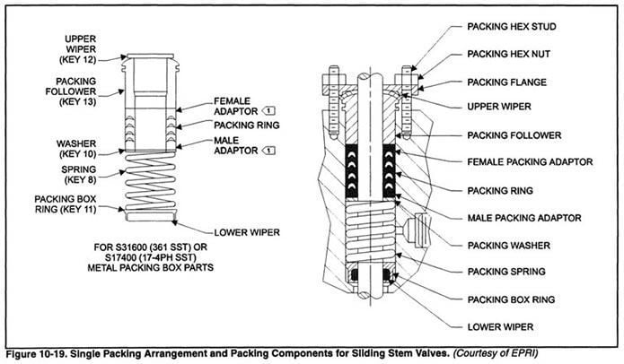
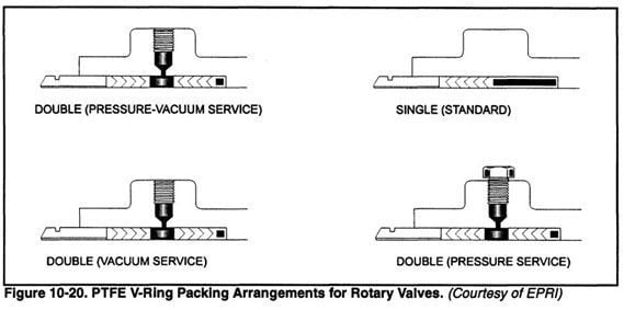
Packing Arrangements SINGLE PACKING This is an economical seal for many applications. Single packing consists of a stack of packing at the top of the packing box supported by either a spring or gland follower. Spring packing can be accomplished by having the packing follower drawn against the bonnet to compress the spring. (This is a variation on the live loaded packing discussed later in this section.) Figures 19 and 20 show single packing arrangements for sliding stem and rotary valves. This type of packing is not adjustable. Springs are not available in all alloy materials. If a special alloy is required, packing with lantern rings should be specified. The packing with lantern rings is also called "jam-type" packing. Jam-type packing will have a gap between the packing follower and bonnet. Single packing arrangements are available in these materials:
  DOUBLE PACKING Double packing arrangements provide a more rugged seal than single arrangements and generally have more packing above than below the lubricating/ lantern ring connection. Figure 10-21 shows a double packing arrangement. 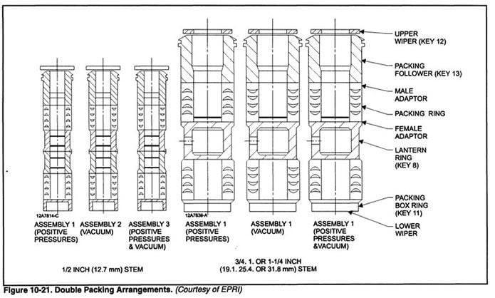 LEAK-OFF PACKING These are specifically designed for applications that require a means of purging packing leakage without allowing process fluid to leak through to the top of the packing box. To meet this criteria, leak-off packing arrangements have the packing above and below a bonnet leak-off connection. There is at least one full set of packing (minimum packing stack height of 1 1/2 stem diameters) below the leak-off connection. There is at least one full set of packing on the valve side of the connection. The smaller amount of packing above the leak-off connection ensures that the adjustment force applied to the packing follower is more completely transmitted to the lower set of packing without creating excessive compression and stem friction in the upper set. Figure 10-22 shows a leak-off packing arrangement. 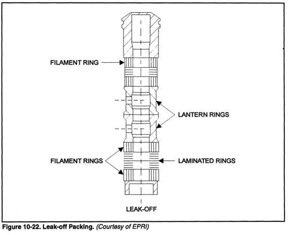 |