This volume is part of the Practical Guide Series developed and published by the ISA, the International Society for Measurement and Control. The Practical Guides were conceived because of a shortage of published material in the field of measurement and control that bridges the gap between theory and actual industrial practice. Many books in the field have catered to the needs of technical students, who need to be oriented to basic control theory and concepts, or college-level readers, who are interested in engineering mainly from a classroom perspective. There are handbooks for practicing engineers that cover measurement and control, but these handbooks often devote only a chapter or two to topics that merit more attention. Within the Practical Guides Series, separate volumes address each of the important topics and give them comprehensive, book-length treatments. Each book in the series can be understood and used by technical students, sales engineers, sales personnel, and managers, and relied upon by those who have "real-live" industrial concerns such as correct application, safety, installation, and maintenance. Another unique feature of the Practical Guides is the stress placed on the actual experience of measurement and control practitioners. The Practical Guides are overseen by various Volume Editors and a Series Technical Editor, who have extensive experience in measurement and control. The Volume Editors have been selected for their specific expertise in the volume topics, and bring together numerous Contributing Writers with even more specialized knowledge. The Series Technical Editor, who is responsible for general technical consistency within each volume and across all volumes, helps guide the Volume Editors. The Practical Guides capture the hard-earned experience of the writers and, by employing examples and recording anecdotal observations, make that experience as applicable for the reader as possible. Case studies, either hypothetical or based on real case histories, are used to illustrate typical situations and show how good planning and practical applications made the difference between success and failure. Some of this information has never been documented before. This volume is designed to be at home in a library, in a classroom, or on the plant floor. The comfortable reading style, large pages, and frequent illustrations will contribute to ease of use. The page design uses graphics to "call out" some of the major points of the text, such as crucial safety checks and important examples. Each Practical Guide gathers widely scattered information in a single text, with bibliographies directing the reader to other sources. |
Chapter 10.7 - Control Valve Features: Fluid Solidification Protection
Fluid Solidification Protection Jacketed Valves and Fittings Jacketed valves are used for conveying petroleum residues, tars, waxes and other solutions which are either extremely viscous or semisolid at ambient temperatures. They must therefore be heated to keep them in a flowable state. Jacketed pipe, fittings and valves are available for a maximum internal, as well as jacket, working pressure of 150 psi. Jacketed valve means a valve body cast with a double wall, or provided with a double wall by welding material around the body to form a passage for a heating (or cooling) medium. In addition, the term refers to valves which are enclosed in split metal jackets having internal heat passageways or electric heating elements. Other common names for these valve types are: "Steam jacketed" or "Vacuum jacketed." Jacketed valves are designed for easier handling of highly viscous materials or to prevent clogging of the valve when handling any material that might solidify at normal operating temperatures. Jacketing is achieved by welding cover plates with pipe couplings over the recess that exists on each side of a butterfly valve body. This way the heat transfer medium is connected to both sides of the valve. 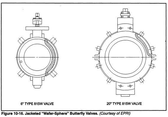 In cryogenic applications, "Vacuum-jacketed" valves are used. A vacuum is created in the space between the body and secondary outer wall. This reduces convective heat transfer from the atmosphere to the internal process fluid. The number and size of couplings for jacketed valves depends on the valve size. For 3"-12" valves, the valve size connections are four diagonal pipe couplings, see Figure 10-17. For 3" and 4" valves, the coupling sizes are 3/8" NPT. For 6"-12" valves, the coupling sizes are 1/2" NPT. Larger valves require eight pipe coupling connections to handle liquid heat transfer flow through the four body recesses. Lugged butterfly valve designs are available with "bolt-on" fabricated jackets clamped on the valve body. A heat transfer cement is applied between the fabricated jacket and the valve body. Valve jackets are rated for 150 psi service. The design is such that the jacket does not interfere with the bolts. Heat transfer is not as efficient in the lugged style as it is in the wafer style design, because of the thinner and irregular body in the lugged design. 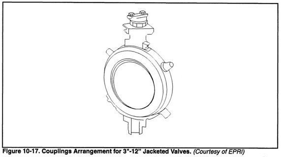 |