This volume is part of the Practical Guide Series developed and published by the ISA, the International Society for Measurement and Control. The Practical Guides were conceived because of a shortage of published material in the field of measurement and control that bridges the gap between theory and actual industrial practice. Many books in the field have catered to the needs of technical students, who need to be oriented to basic control theory and concepts, or college-level readers, who are interested in engineering mainly from a classroom perspective. There are handbooks for practicing engineers that cover measurement and control, but these handbooks often devote only a chapter or two to topics that merit more attention. Within the Practical Guides Series, separate volumes address each of the important topics and give them comprehensive, book-length treatments. Each book in the series can be understood and used by technical students, sales engineers, sales personnel, and managers, and relied upon by those who have "real-live" industrial concerns such as correct application, safety, installation, and maintenance. Another unique feature of the Practical Guides is the stress placed on the actual experience of measurement and control practitioners. The Practical Guides are overseen by various Volume Editors and a Series Technical Editor, who have extensive experience in measurement and control. The Volume Editors have been selected for their specific expertise in the volume topics, and bring together numerous Contributing Writers with even more specialized knowledge. The Series Technical Editor, who is responsible for general technical consistency within each volume and across all volumes, helps guide the Volume Editors. The Practical Guides capture the hard-earned experience of the writers and, by employing examples and recording anecdotal observations, make that experience as applicable for the reader as possible. Case studies, either hypothetical or based on real case histories, are used to illustrate typical situations and show how good planning and practical applications made the difference between success and failure. Some of this information has never been documented before. This volume is designed to be at home in a library, in a classroom, or on the plant floor. The comfortable reading style, large pages, and frequent illustrations will contribute to ease of use. The page design uses graphics to "call out" some of the major points of the text, such as crucial safety checks and important examples. Each Practical Guide gathers widely scattered information in a single text, with bibliographies directing the reader to other sources. |
Chapter 5 - Control Valve Actuators
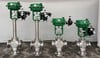
A control valve actuator is a fluid or electrically powered device that supplies the required force to position a valve shaft or stem. Distinct from an isolation valve actuator, a control valve actuator provides motion to a certain position in proportion to a signal sent from a system controller to the actuator. An isolation valve actuator usually provides one of two positions: full open or full closed. In contrast, a control valve actuator is seldom full open or closed but in an intermediate position required by the controller to satisfy the process system conditions. A control valve actuator that is not primarily used for tight shutoff usually produces less output force than an isolation valve actuator. However, it provides accurate position control. The selection process for a control valve actuator considers many attributes. Does the actuator have sufficient travel? Does the actuator generate sufficient force or torque to satisfy the valve's need for the specific application? Beyond these basic considerations are many more that will identify which actuator is best suited for the application. There are no bad or good actuator styles; they all are good for specific applications. This chapter discusses many styles and describes their characteristics to aid in the selection process. Control valve actuators have evolved recently to keep pace with the evolution of control valves. The changes include more styles of rotary motion, higher precision actuators using hydraulics, and motor/gear drives. Signals and Power Sources All control valves receive a signal from a controller. This is the characteristic that distinguishes control valves from all other valves. Control valve actuators require two outside influences, a signal and a power source. The signal is typically an analog pneumatic 3 to 15 psig or a 4 to 20 milliampere (mA) electric current. In addition, digital signals are beginning to emerge and will soon make a significant impact on control technology. The most common power for actuators is compressed air in the 60 to 100 psig range. AC and DC electric power are also used, as is fluid hydraulic power. The hydraulic power can come from a central source or can be generated at the actuator from electric power. Compressed air is the lowest-cost power source and is used in the vast majority of applications. However, electricity and hydraulics have certain virtues that are not available in pneumatics. For many applications the pneumatic signal also serves as the actuator's power. |