This volume is part of the Practical Guide Series developed and published by the ISA, the International Society for Measurement and Control. The Practical Guides were conceived because of a shortage of published material in the field of measurement and control that bridges the gap between theory and actual industrial practice. Many books in the field have catered to the needs of technical students, who need to be oriented to basic control theory and concepts, or college-level readers, who are interested in engineering mainly from a classroom perspective. There are handbooks for practicing engineers that cover measurement and control, but these handbooks often devote only a chapter or two to topics that merit more attention. Within the Practical Guides Series, separate volumes address each of the important topics and give them comprehensive, book-length treatments. Each book in the series can be understood and used by technical students, sales engineers, sales personnel, and managers, and relied upon by those who have "real-live" industrial concerns such as correct application, safety, installation, and maintenance. Another unique feature of the Practical Guides is the stress placed on the actual experience of measurement and control practitioners. The Practical Guides are overseen by various Volume Editors and a Series Technical Editor, who have extensive experience in measurement and control. The Volume Editors have been selected for their specific expertise in the volume topics, and bring together numerous Contributing Writers with even more specialized knowledge. The Series Technical Editor, who is responsible for general technical consistency within each volume and across all volumes, helps guide the Volume Editors. The Practical Guides capture the hard-earned experience of the writers and, by employing examples and recording anecdotal observations, make that experience as applicable for the reader as possible. Case studies, either hypothetical or based on real case histories, are used to illustrate typical situations and show how good planning and practical applications made the difference between success and failure. Some of this information has never been documented before. This volume is designed to be at home in a library, in a classroom, or on the plant floor. The comfortable reading style, large pages, and frequent illustrations will contribute to ease of use. The page design uses graphics to "call out" some of the major points of the text, such as crucial safety checks and important examples. Each Practical Guide gathers widely scattered information in a single text, with bibliographies directing the reader to other sources. |
Chapter 10.5 - Control Valve Features: Flanged End Connections
Flanged End Connections Flanged valves are perhaps the most widely used. Flanges used to mate valves with adjacent piping and/or equipment must conform to the following:
Flanged end connections are tightened by a number of bolts which individually require less tightening torque than an individual threaded joint for a given application. For this very reason flanged end connections can be used for most valve sizes, pressures and temperatures. However, flanged end connections have their limitations as well. At temperatures above 660° F, creep relaxation of bolts, gasket and flanges can lower the bolt load. Flanged joints subjected to excessive stresses can develop leakage problems at high temperatures. To avoid fabricating flanges for each service pressure, pipe and pipe diameter, a rating system was developed. ANSI / ASME standardized flanges for ratings of 125, 150, 250, 300, 400, 600, 800, 900, 1500, 2500 and 4500 pounds. These pressure ratings decrease in magnitude with increases in service temperatures. Depending on flange material, a 150 lb flange can have a rating of 275 psi at 100F and a rating of 150 psi at 500F. Similarly, a 2500 lb flange can have a rating of 6000 psi at 100F and 2500 psi at 950°. THE MISSION OF FLANGES The use of flanged valves is particularly convenient for quickly removing a defective valve from a line without a protracted shut-down of service. Flanged valves are available in cast irons, bronzes, castable alloys and cast or forged steels. Diameters and drilling of valve end flanges are in accordance with one of several flange standards listed in the Valve End Connection Types section of this chapter. Flanges are designed to ensure a tight joint that can be conveniently separated for piping changes and repairs. Yet poor selection of flanges, bolts and gaskets, plus imprudent joint design can be cause for problems. TYPES OF FLANGES Flange facings are available in several configurations, the most common being:
The most widely used (standard) facing is the raised face with a spiral, serrated surface with from 24 to 40 grooves per inch. 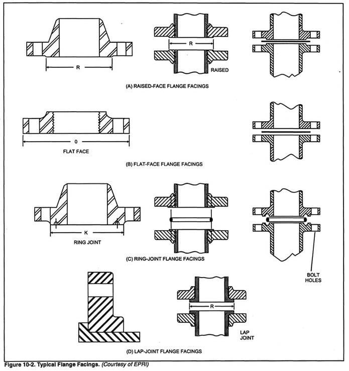 Raised face flange (a) - Raised face flange connections incorporate the most popular flanges and are used where threaded, flat face or ring-type flange connections are not required. Dimensions of raised face flanges conform to the American Standard ANSI/ASME B-16.5. Figure 10-3 illustrates a raised face flange. Raised face flange facings are the most popular. 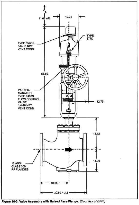 Flat face flange (b) - Flat face flanges are used to match only specific piping/ valving systems. For example, Class 125 cast iron material systems. However, flat face Class 150 pipe flanges are used to mate against Class 125 cast iron to prevent cast iron cracking. Ring joint flange (c) - Ring joint flange connections are used in the petroleum refining industry for high temperature (above 600° F) or high pressure (above 1500 psig) service. Valve manufacturers' recommendations must also be followed. Client requirements should be scrutinized where the process conditions require ring-type flanges. Ring joint flanges are designed in accordance to ANSI / ASME B16.5 and are manufactured in welding-neck, slip-on, threaded and lapped joint designs. The rings may have a bonded elastomer coating to reduce corrosion. The rings are available in oval or octagonal shapes manufactured from soft metal. Tongue and groove flanges - Tongue and groove flanges are widely used in chemical services. The valve flanges should have the tongue, the pipe flanges the groove. They are used to restrain gaskets which cold flow. Their pressure span ranges from 250 to 2500 psig. ANSI / ASME B16.5 defines their temperature ratings. FLANGE INSTALLATION Flange Alignment - Proper flange installation involves precise flange alignment to avoid problems. Prior to bolting, flanges should be carefully aligned so that excessive bolting stresses in valves, fittings and pipe flanges are not generated. Use of thread lubricant cuts friction, protects threads and makes joints easier to break for necessary maintenance. Figure 10-4 shows a series of installation steps used to ensure proper alignment. 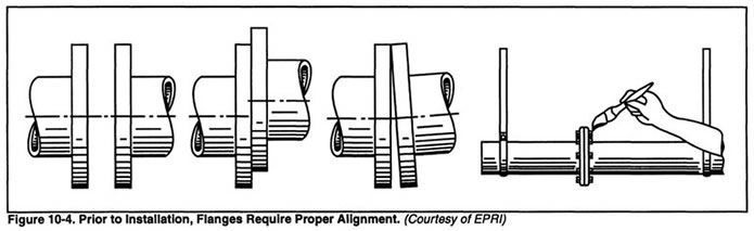 Gaskets - The gasket selected must conform to the following requirements:
The decision of which gasket material to select depends on service temperature, pressure and the aggressiveness of the sealed medium. Gasket materials range from soft rubber for cold water service to narrow solid iron rings for high pressure steam joints. FLANGELESS (OR WAFER-STYLE) VALVE BODIES Flangeless or wafer-style valve bodies are common to rotary-shaft control valves. Flangeless bodies are held between ANSI / ASME class flanges by through bolts. The bolts are long studs that hold the assembly together. Flangeless connections are available in butterfly and some ball valve designs. Flangeless construction is convenient for bar stock valves because it requires a reduced amount of machining or welding. 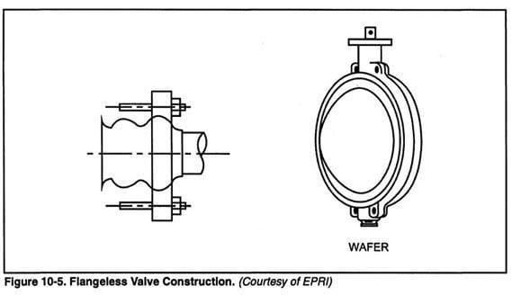 WELDED CONNECTIONS Welded end valves are used for installations in a pipeline to eliminate all possibility of leakage. Welded end valves are specified for high pressure and high temperature applications as well as for toxic, flammable and explosive fluid services where no leakage to the environment can be tolerated. During the welding installation process, extremely high temperatures can be generated locally at the valve and may damage the valve trim parts. Following the welding process, another potential problem can be slag and debris entrainment in the valve trim and pipe. Slag and debris can be removed by flushing.  The welding process involves three major phases:
Preheating is accomplished by heating the two parts to be welded to a temperature range of between 300-500°. Although this temperature is not harmful to most metal parts, certain elastomers and plastic components may have lower temperature limits. These internal valve body parts include seal rings, "O"-rings, gaskets, packing rings and the like. Where heating of the valve to accommodate field welding can be damaging, factory installed nipples and/or reducers move the field welding and stress relieving heat away from the valve. The post weld heat treating process is accomplished at extremely high temperatures of up to HOOF and of several hours holding time. Although the heat is applied to only the welded area, heat can be conducted back into the valve body. This transfer can create the following problems:
For most applications, if post-weld heat treatment is required, all trim parts must be removed to avoid damage. When reassembling the valve, an extra set of gaskets and packing must be available for use to avoid leaks or erosion at the gasket surfaces, the bore of the packing box or the valve stem. Butt Welding - Butt-weld valve end connections are standardized in ANSI / ASME B 16.34. Butt-welded ends are available in both cast and forged steel with ends specifically machined and bevelled for butt-welding. Butt-welded joints should have a uniform thickness. If the connected part thicknesses differ by more than 20%, then it is mandatory to make their abutting edges the same (build up the thinner part). Butt-welded valve connections are common where high pressure, high temperature fluids are encountered, as in power generating plants for steam and feedwater service. Butt-welding is of particular value for vacuum service. Welding procedures should be developed and included in the valve specification, especially when ordering new valves tailored for specific project requirements. The valve manufacturer must submit welding details to be reviewed for conformance to the specifications. The primary disadvantage is that welded connections must be cut and then rewelded each time the valve is removed. Figure 10-6a illustrates a valve with butt-welded end connections. 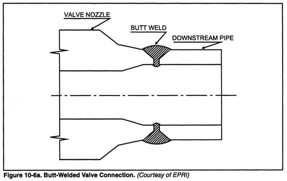 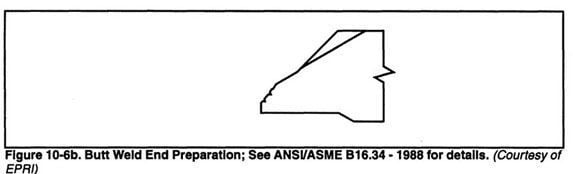 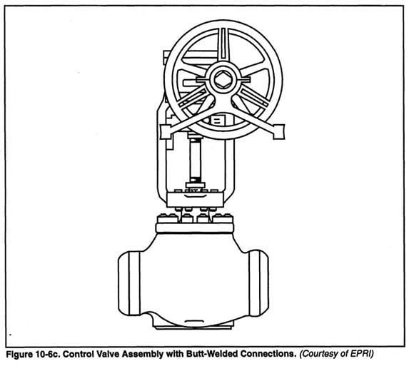 Socket Welded - Socket welded valve connections are standardized in ANSI / ASME B 16.34 for valve sizes up to 2 inches. This standard entitled "Valves -Flanged, Threaded and Welded End", requires that the wall thickness of the socket must be equal to or greater than 1.25 times the minimum pipe wall. The socket weld joint is not as resistant to bending stresses or thermal transients as the butt welded joint. For some fluids, the crevice between the pipe and valve socket can promote corrosion. Figure 10-7 shows typical socket weld valve connections. 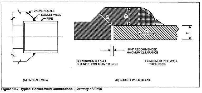 WELD ON EXTENSIONS Pipe Nipples - In control valve installations where valve body size is identical to the pipe but the materials of construction differ, the end connections are usually butt-welded and a pipe nipple is used at the joint to facilitate a dissimilar metal weld. Pipe nipples of the same material as the pipe are usually 6" long and should be ordered with the valve. Concerns dealing with dissimilar metal welds are similar to those listed for reducers and expanders, discussed in the next section. It is prudent to let the valve manufacturer perform the more complicated metallurgical fabrication. Reducers and expanders - In control valve applications where valve size is different from the adjoining pipe, reducers or expanders are required to complete the installation. Concentric reducers and expanders are commonly used for clean (free of suspended solids) and non-viscous fluids in either horizontal or vertical installations. Eccentric reducers and expanders are used for viscous fluids or slurry applications. The flat bottom of the eccentric reducer discourages solids accumulation when installed in horizontal piping runs. When a control valve installation requires reducers or expanders to mate with the adjoining pipe, the control valve should be ordered with these components shop welded to the valve. Although the manufacturer will charge a premium for the reducers, it is worth the initial cost. Possible field fabrication errors or mishandling by crafts personnel, which could cause damage to the valve itself, are minimized. In addition, when a dissimilar metal weld is required for valve installation, it is advisable to let the vendor assume responsibility for the welding process. Factory conditions allow production of these welds (including pre and post heat treating) under much higher standards than those achieved in the field. Of course, the reducer/expander material ordered must be the same as that of the pipe in the final installation. This practice allows furnace relief of the body nipple or reducer assembly. The body is then machined relative to the bonnet gasket and seat joint, making the valve assembly in true alignment. Figure 10-8 indicates typical concentric and eccentric reducers. 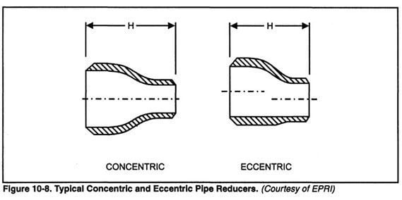 |