This volume is part of the Practical Guide Series developed and published by the ISA, the International Society for Measurement and Control. The Practical Guides were conceived because of a shortage of published material in the field of measurement and control that bridges the gap between theory and actual industrial practice. Many books in the field have catered to the needs of technical students, who need to be oriented to basic control theory and concepts, or college-level readers, who are interested in engineering mainly from a classroom perspective. There are handbooks for practicing engineers that cover measurement and control, but these handbooks often devote only a chapter or two to topics that merit more attention. Within the Practical Guides Series, separate volumes address each of the important topics and give them comprehensive, book-length treatments. Each book in the series can be understood and used by technical students, sales engineers, sales personnel, and managers, and relied upon by those who have "real-live" industrial concerns such as correct application, safety, installation, and maintenance. Another unique feature of the Practical Guides is the stress placed on the actual experience of measurement and control practitioners. The Practical Guides are overseen by various Volume Editors and a Series Technical Editor, who have extensive experience in measurement and control. The Volume Editors have been selected for their specific expertise in the volume topics, and bring together numerous Contributing Writers with even more specialized knowledge. The Series Technical Editor, who is responsible for general technical consistency within each volume and across all volumes, helps guide the Volume Editors. The Practical Guides capture the hard-earned experience of the writers and, by employing examples and recording anecdotal observations, make that experience as applicable for the reader as possible. Case studies, either hypothetical or based on real case histories, are used to illustrate typical situations and show how good planning and practical applications made the difference between success and failure. Some of this information has never been documented before. This volume is designed to be at home in a library, in a classroom, or on the plant floor. The comfortable reading style, large pages, and frequent illustrations will contribute to ease of use. The page design uses graphics to "call out" some of the major points of the text, such as crucial safety checks and important examples. Each Practical Guide gathers widely scattered information in a single text, with bibliographies directing the reader to other sources. |
Chapter 23 - Everything You Ever Wanted to Know About Regulators
Few members of the valve family are as unknown or misunderstood as the regulator. Widely used throughout industry as air sets for pressure control of the instrument air to actuators of diaphragm control valves, regulators are also available in a number of other forms designed to control pressure, back pressure, temperature, or flow for either utility or process applications. Regulators frequently use the same types of bodies, materials, and internals as control valves and can be used on most gases (including steam) and liquids. ISA S5.1, "Instrumentation Symbols and Identification" [Ref. 1], also demonstrates this kinship with regard to tagging, where regulators are designated PCV, TCV, FCV, and so on while control valves for the same service are called out as PV, TV, or FV. The purpose of this chapter is to review the operation and performance characteristics of various types of regulators and discuss common regulator applications to familiarize the reader with this versatile product. The advantages and disadvantages of regulators as compared to control valves will also be summarized to offer some guidelines regarding when each individual style should be selected. Operation ANSI/FCI-86-2, "Regulator Terminology" [Ref. 2], defines a regulator as a valve with a positioning actuator that uses energy from the controlled fluid to move the closure member. In the case of a pressure regulator, this energy is supplied by the pressure of the controlled variable; a temperature regulator uses the energy supplied by changes in the temperature energy of the controlled variable. A pressure regulator may be described as a simple proportional control loop in that it contains a sensor (diaphragm), controller (range spring), and final control element (closure member). Figure 23-1, a direct-operated pressure-reducing regulator, offers a good illustration of how this valve operates. The function of this particular unit is to reduce what may be a varying inlet pressure (p1) to a lower controlled outlet pressure (p2) - That outlet pressure is determined by the amount of compression applied to the range spring by the adjusting screw so the regulator becomes a force balance device. 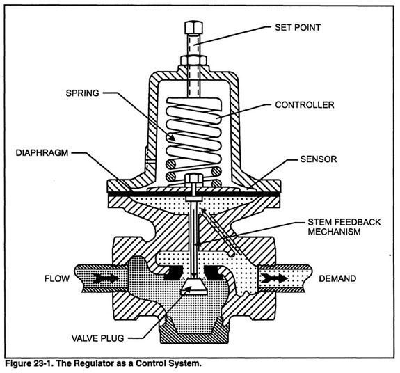 This pressure regulator features a reverse-acting plug and is normally an open valve. This type of plug is situated so that the valve stem extends through the orifice. The pressure downstream of the orifice (p2) is applied to the diaphragm and opposes the spring compression so as to throttle the valve by moving the valve plug closer to the valve seat as p2 rises. If p2 increases above the value determined by the spring compression, the valve plug will be positioned into the valve seat and the valve will close. A decrease in the value of p2 will enable the spring to push the valve plug out of the seat and open the valve. The set point is achieved when the amount of spring compression is balanced by the pressure of p2 applied to the diaphragm. |