This volume is part of the Practical Guide Series developed and published by the ISA, the International Society for Measurement and Control. The Practical Guides were conceived because of a shortage of published material in the field of measurement and control that bridges the gap between theory and actual industrial practice. Many books in the field have catered to the needs of technical students, who need to be oriented to basic control theory and concepts, or college-level readers, who are interested in engineering mainly from a classroom perspective. There are handbooks for practicing engineers that cover measurement and control, but these handbooks often devote only a chapter or two to topics that merit more attention. Within the Practical Guides Series, separate volumes address each of the important topics and give them comprehensive, book-length treatments. Each book in the series can be understood and used by technical students, sales engineers, sales personnel, and managers, and relied upon by those who have "real-live" industrial concerns such as correct application, safety, installation, and maintenance. Another unique feature of the Practical Guides is the stress placed on the actual experience of measurement and control practitioners. The Practical Guides are overseen by various Volume Editors and a Series Technical Editor, who have extensive experience in measurement and control. The Volume Editors have been selected for their specific expertise in the volume topics, and bring together numerous Contributing Writers with even more specialized knowledge. The Series Technical Editor, who is responsible for general technical consistency within each volume and across all volumes, helps guide the Volume Editors. The Practical Guides capture the hard-earned experience of the writers and, by employing examples and recording anecdotal observations, make that experience as applicable for the reader as possible. Case studies, either hypothetical or based on real case histories, are used to illustrate typical situations and show how good planning and practical applications made the difference between success and failure. Some of this information has never been documented before. This volume is designed to be at home in a library, in a classroom, or on the plant floor. The comfortable reading style, large pages, and frequent illustrations will contribute to ease of use. The page design uses graphics to "call out" some of the major points of the text, such as crucial safety checks and important examples. Each Practical Guide gathers widely scattered information in a single text, with bibliographies directing the reader to other sources. |
Chapter 10.20 - Control Valve Features: Hydraulic Snubbers
Hydraulic Snubbers Snubbers are used where dynamic instability causes the valve stem to jump or oscillate. Installation of a hydraulic snubber between the valve yoke and the diaphragm casing is an effective method of suppressing the vertical oscillation. 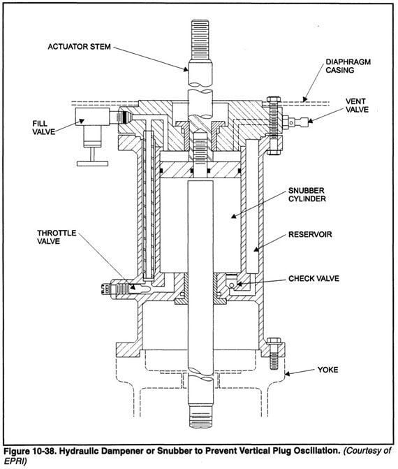 Hydraulic snubbers are used on severe control valve applications to alleviate problems in a valve plug by damping vertical instability. Very few applications require snubbers. Most cases of dynamic instability are handled by using a large actuator, a higher loading pressure with a heavier spring or by reversing the valve in the line so that flow impinges on the bowl of the body. The following categories of valve may require a hydraulic snubber:
The snubber consists of a hydraulic cylinder attached between the valve bonnet and the actuator stem, and/or is added between the diaphragm case and spring housing. The extended actuator rod, passing through the cylinder and sealed at both penetrations, has a piston mounted on it. It is filled with oil so that a wide clearance piston carried by the stem will damp the valve movement. As the piston moves, it displaces oil from one side of the piston, through adjustable snubbed orifices back to the other side. The snubber is self-contained and requires no external power. Another style of snubber uses needle valves between the chambers, above and below the hydraulic piston. The closure of these needle valves is adjustable to obtain the desired damping action. |